February 14, 2012 6816985H01-F
6.4-22 700/800 MHz Troubleshooting Charts: 700/800 MHz Transmitter RF Troubleshooting Chart
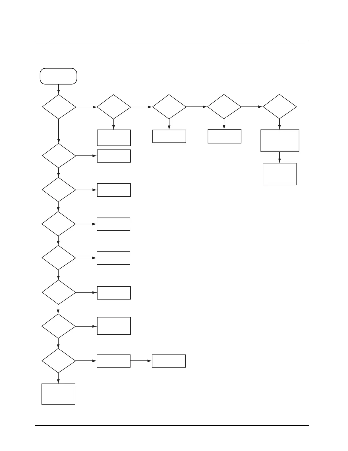
6.4.23700/800 MHz Transmitter RF Troubleshooting Chart
MAEPF-27349-O
No/Low TX Power
Is B+ at
U101 pins 6,7,
and 14?
Is Vdc
at TP101
>2V?
Is Vdc
at U101 pin 1
>2V?
Is Vdc
at C142
>1V?
Is
RF at U101
pin 16 >2
dBm?
No
No
Ye s
Ye s
Ye s
Ye s
Is
RF at U101
pin 6 >20
dBm?
Ye s
Ye s
Ye s
Ye s
No
Is
TX current
>300mA?
Is RF
input drive at
U101 pin 16
>2dBm?
Is there
continuity across
U106?
Go to Frequency
Generation Unit
Chart
No
Check L107
and L108
No
Check E101,
E102 and L103
No
Check ALC IC
No
Check R114,
R115, and R119
No
Replace Q101
No
Go to Frequency
Generation Unit
Chart
No
Check L110,
L112, and C132
Replace U101
Is B+
at C128?
Change U106
No
Ye s
Ye s
No
Is
voltage drop
across CR101
>0.5V?
Is
there RF
at connector
J101?
Check U102
and the ALC IC
Check L104, L114,
C105, C103, C107,
C108, and C104
Remove SH102
Check CR102,
and R106
Yes
Check C128,
C127, C219,
and C142
*
*
*
**
*
*
*
*
For Analysis, shields SH103 and SH104 need to be removed.
= Transmitter enable Low.
 Loading...


