MTR3000 Backplane: Description 6-7
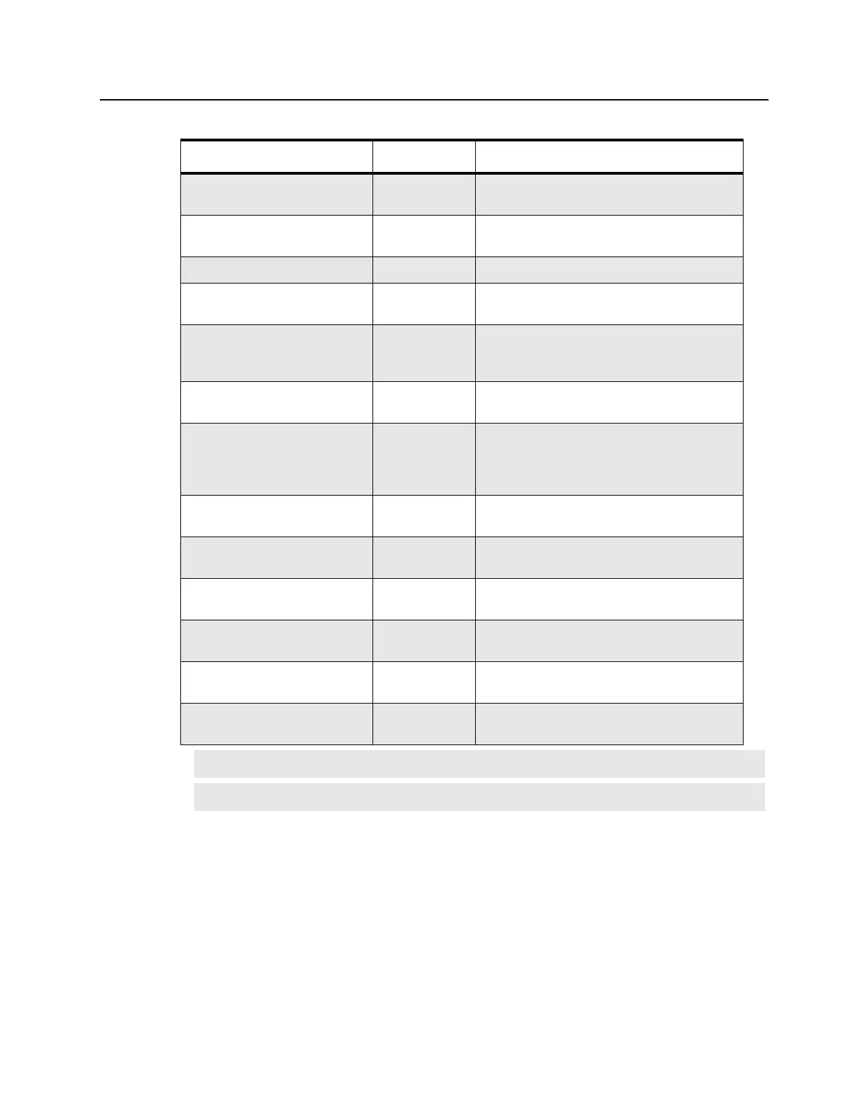
PA Reset* Digital Resets logic devices within the PA; TTL
active low
Ptemp+ Analog Input to SCM from peripheral temperature
sensing device on circulator
Reset* Digital System reset from SCM; TTL active low
RF Relay Control In Digital From Controller to Option 1 and Option 2 to
signal RF Relay is activated; TTL active high
RF Relay Control Out Digital From Option 1 or Option 2 to SCM as open
collector (active low) to indicate RF Relay is
activated (or for some other control usages).
RSSI Analog From SCM; DC voltage proportional to the
receive RF signal strength; 0 to 5 VDC
Rx Audio Analog Receive Audio – A received RF signal at 60%
RSD produces a 330mVrms audio output.
The local microphone is summed in with the
receive audio.
Serial ID Digital Serial ID data to SCM from backplane
interface board serial ID device
SPI CLK (Serial Peripheral
Interface Clock)
Digital SCM SPI bus clock; Low-to-high transition
shifts data; 310 kHz (Minimum); standard TTL
Tx Audio Analog Transmit Audio – 80mVrms produces 60%
transmit deviation.
Tx Data Analog Low Speed Trunking Data or PL or DPL –
80mVrms produces12% transmit deviation
Wireline ID Analog To SCM ADC from WIB; module ID
determined by specific voltage; 0 to 5 VDC
Wireline1 Latch CS* Digital Chip select for SPI latch on WIB; TTL active
low
Note (*) Indicates an active low signal
Note
(**) Not supported.
Table 6-2 Backplane Interface Board Signal Descriptions (Continued)
Signal Name Type Function/Signal Levels
 Loading...


