6-6 MTR3000 Backplane: Description
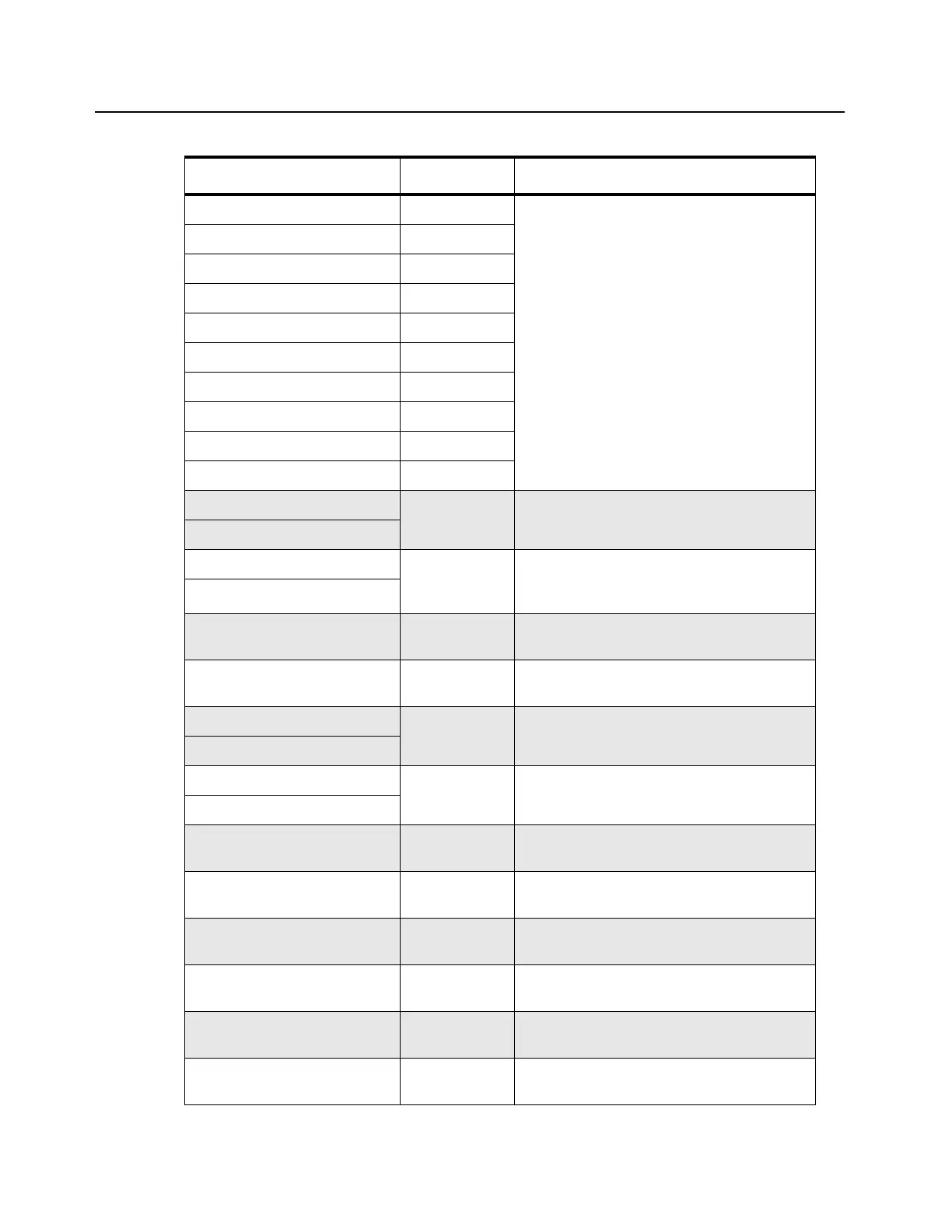
GPI_1 Digital General purpose programmable inputs/
outputs which can be configured through
CPS to one of several functions. Input levels
are 0 to 5V. Less than 0.7V is a logic low and
greater than 2V is a logic high.
GPIO_2 Digital
GPIO_3 Digital
GPI_4 Digital
GPIO_5 Digital
GPIO_6 Digital
GPIO_7 Digital
GPIO_8 Digital
GPIO_9** Digital
GPIO_10 Digital
Line 1+ Analog 4-wire Phone Line (differential) inputs; 600 Ω
typical impedance (country-specific)
Line 1-
Line 2+ Analog 2-wire Phone Line (differential) inputs/outputs
or, 4-wire Phone Line outputs; 600 Ω typical
impedance (country-specific)
Line 2-
MISO (Master In Slave Out) Digital SPI data from Slave devices to Master
(SCM); standard TTL
MOSI (Master Out Slave In) Digital SPI data from Master (SCM) to Slave
devices; standard TTL
OP1 CS1* Digital From SCM to Option 1 module; SPI bus chip
selects; TTL active low
OP1 CS2*
OP2 CS1* Digital From SCM to Option 2 module; SPI bus chip
selects; TTL active low
OP2 CS2*
Opt IRQ* Digital Interrupt request to SCM from Option cards;
TTL active low
Option1 ID Analog Option 1 ID to SCM ADC; module ID
determined by specific voltage; 0 to 5 VDC
Option2 ID Analog Option 2 ID to SCM ADC; module ID
determined by specific voltage; 0 to 5 VDC
PA AD CS* Digital From SCM; during SPI signalling, selects
ADC converter in PA; TTL active low
PA DA CS* Digital From SCM; during SPI signalling, selects
DAC converter in PA; TTL active low
PA Enable* Digital From SCM; controls final module bias in PA;
TTL active low
Table 6-2 Backplane Interface Board Signal Descriptions (Continued)
Signal Name Type Function/Signal Levels
 Loading...


