MTR3000 Backplane: Description 6-5
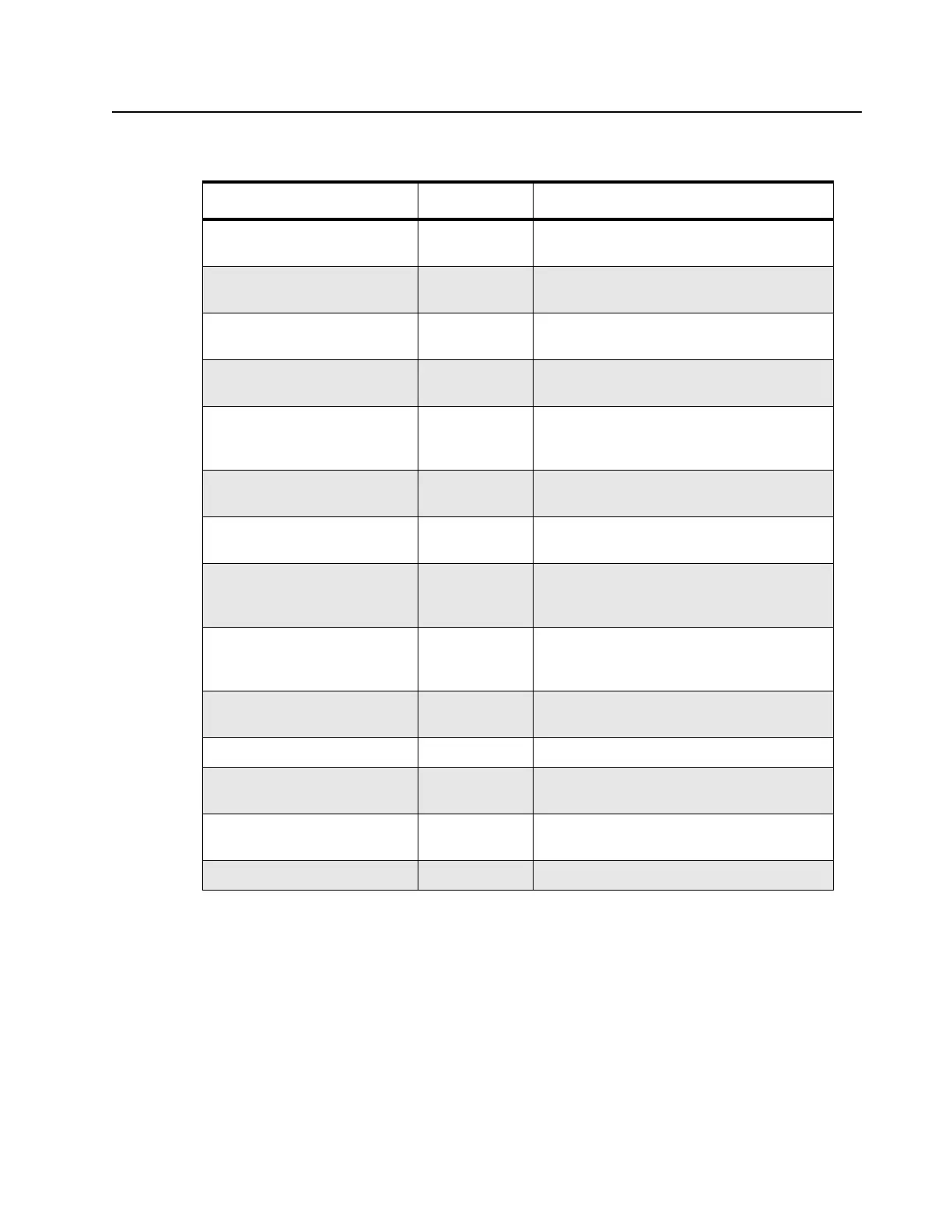
Table 6-2 Backplane Interface Board Signal Descriptions
Signal Name Type Function/Signal Levels
5_VDC Power +5.1 VDC from Power Supply (2.0A total
maximum)
8_VDC Power +8 VDC from Regulator U102-3 (0.25A total
maximum)
10V_VDC Power +10 VDC from U101-3 to Exciter Module via
SCM (0.70A total maximum)
10V_VDC Power +10 VDC from U101-3 to Receiver Module
via SCM (0.70A total maximum)
14.2VDC Power +14.2 VDC from Power Supply (8A total
maximum to PA and backplane interface
board)
AC_Fail Digital AC status signal from power supply to SCM;
Active high indicates AC Mains failure
Accessory_14.2VDC Analog +14.2 VDC from Power Supply to Systems
connector J5 (1.0A total maximum)
Antenna_Relay Digital Open-collector control signal from Controller
to SCM to antenna relay; Low to energize
relay
Aux Rx Audio Analog Auxiliary Receive Audio – A received RF
signal at 60% RSD produces a 330mVrms
audio output.
Carrier Detect Switch Digital From SCM to indicate carrier present; TTL
active high
Chassis GND Power Station ground
Emph Tx Audio Analog Emphasized Tx Audio - 80mVrms @ 1 kHz
produces 60% transmit deviation.
Ext PTT* Digital Interrupt request to SCM to key transmitter;
TTL active low
GND Power Station ground
 Loading...


