6-4 MTR3000 Backplane: Description
6.1.1.2 Backplane Interface Board Connectors Information
Each connector on the backplane interface board has been assigned a connector designation
number. For rear connectors, the connector number is stamped onto the metal shield covering the
rear of the backplane interface board. Labels for connectors which accept the plug-in modules are
viewable when the front panel is removed. Table 6-1 lists each connector and its assigned
designation number.
Table 6-2 provides a detailed description of all of the backplane interface board signals, arranged in
alphanumeric order.
As shown, each connector Pin is defined by signal name, input or output (with reference to
connector), and the to/from location(s).
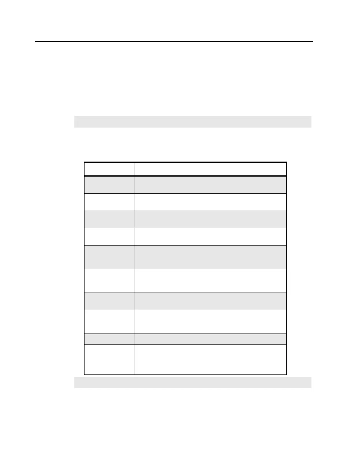
Table 6-1 Assigned Connector Number Vs. Function/Location Information
Note
An asterisk (*) indicates an active on low signal.
Connector Function/Location
J1 96-Pin Eurocard connector; accepts plug-in Option Board 1
(From front of base station/repeater, behind front panel)
J2 96-Pin Eurocard connector; accepts plug-in Option Board 2
(From front of base station/repeater, behind front panel)
J3 96-Pin Eurocard connector; accepts plug-in Station Control
Module (From front of base station/repeater, behind front panel)
J4 96-Pin Eurocard connector; accepts plug-in Wireline Interface
Board (From front of base station/repeater, behind front panel)
J5 96-Pin Eurocard connector; provides System connection to
external communications equipment (At the back of the base
station/repeater)
J6 4-position terminal block with plug; accepts customer phone line
connections. The plug accepts a wire diameter range of 12 to
26 AWG (At the back of the base station/repeater)
J7 25-Pin connector; for connecting to an external device such as
a trunking controller, tone remote adaptor or phone patch.
P7 10-Pin connector; provides connection to Power Amplifier (PA);
routes SPI bus and chip selects from Station Control Module to
PA (At the back of the base station/repeater)
P8 8-Pin connector; provides connection to Power Supply (PS)
P10 Antenna Relay 3-Pin connector; supplies control signal and
power to antenna relay module; provides connection to a
peripheral temperature sensing device such as found in an
external circulator (At the back of the base station/repeater)
Note Peripheral temperature sensing device is not available for the 800/900 MHz band.
 Loading...


