9-20 MTR3000 Radio Frequency Distribution System (RFDS) Equipment: Field Tuning Procedures
b. Rough Tuning
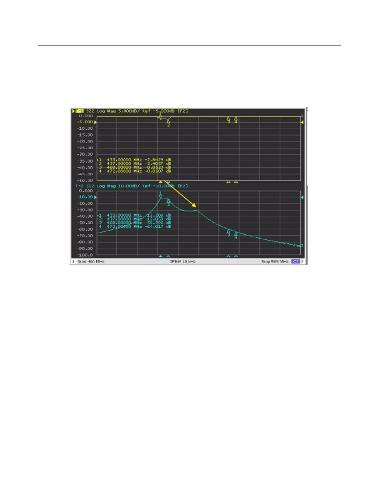
i. Adjustment of the tuning screws changes the position of the frequency peaks on the
displayed curves. As an example, note that when screw 4 is adjusted counterclockwise,
the resonance peak moves to the left and if turned clockwise, the peak moves to the
right as indicated by the yellow arrow in Figure 9-11.
Figure 9-11 Passband tuning of tuning screw 4
ii. Adjust tuning screw 4 until the peak moves into the 468–472MHz range (the area
between Marker 3 and Marker 4). Refer to Figure 9-12.
 Loading...


