MANUAL-75-v2.0 39 of 82
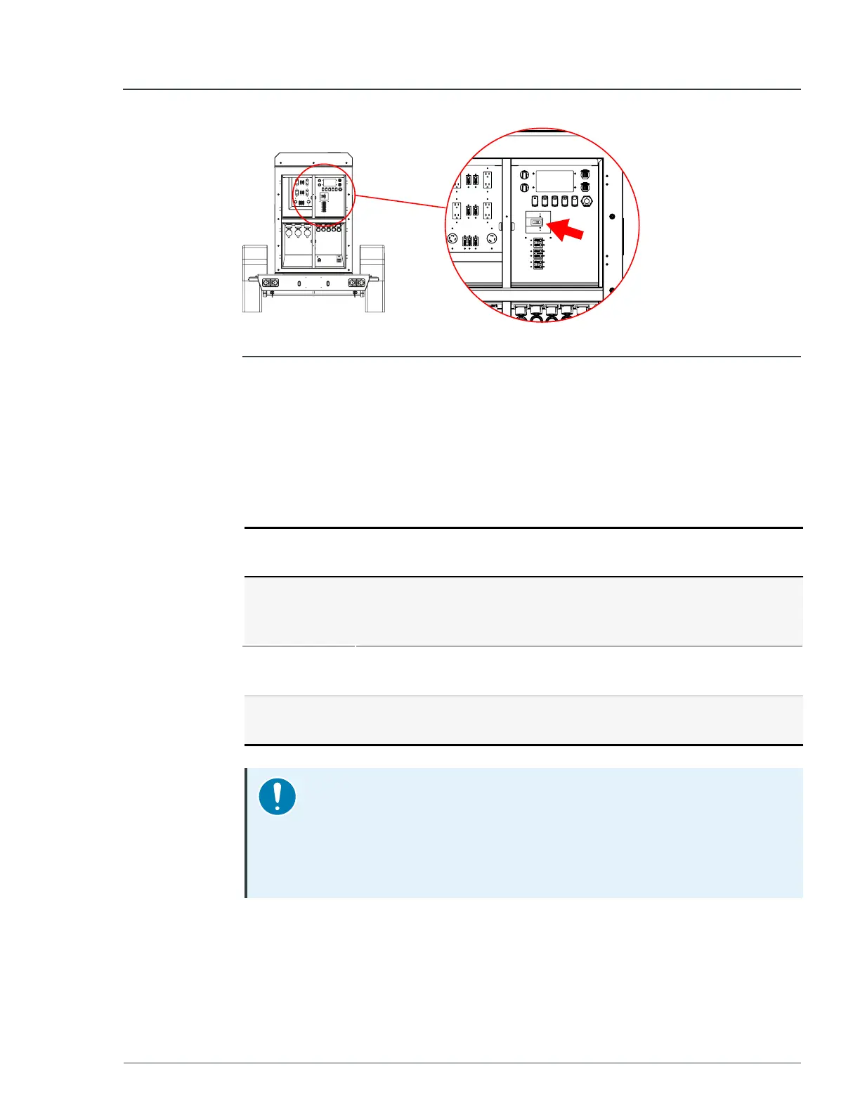
Figure 18 - Location of main breaker
4. Switch all
Twist
Lock
breakers to the
OFF
position.
5. Make all intended electrical connections to the cam-locks and twist-locks
per the instructions in Sections 3.5 and 3.6 of this manual.
6. Turn the
Control
dial to the
STANDBY
position.
When the system starts, the screen displays available energy information. The
unit is now ready to begin outputting power.
7. Turn the
Voltage
Mode
knob to one of the desired voltage outputs:
Voltage
output
Powered connections
240V/120V-
1P
l
All cam-lock connections.
l
Cam-lock connections
1
and
2
or
1
and
3
for 240V.
l
Twist-lock connections
1
and
2
.
208V/120V-
3P
l
All cam-lock connections.
l
All three twist-lock connections.
480V/277V-
3P
l
All cam-lock connections.
Notice
The unit cannot be enabled if there is a mismatch between the voltage
mode knob position and previously set voltage.
To confirm a new selection, press
Switch 1
, otherwise revert the knob
to match the voltage on the display.
3 Quick start MP75-600 - User Manual