28 of 82 MANUAL-75-v2.0
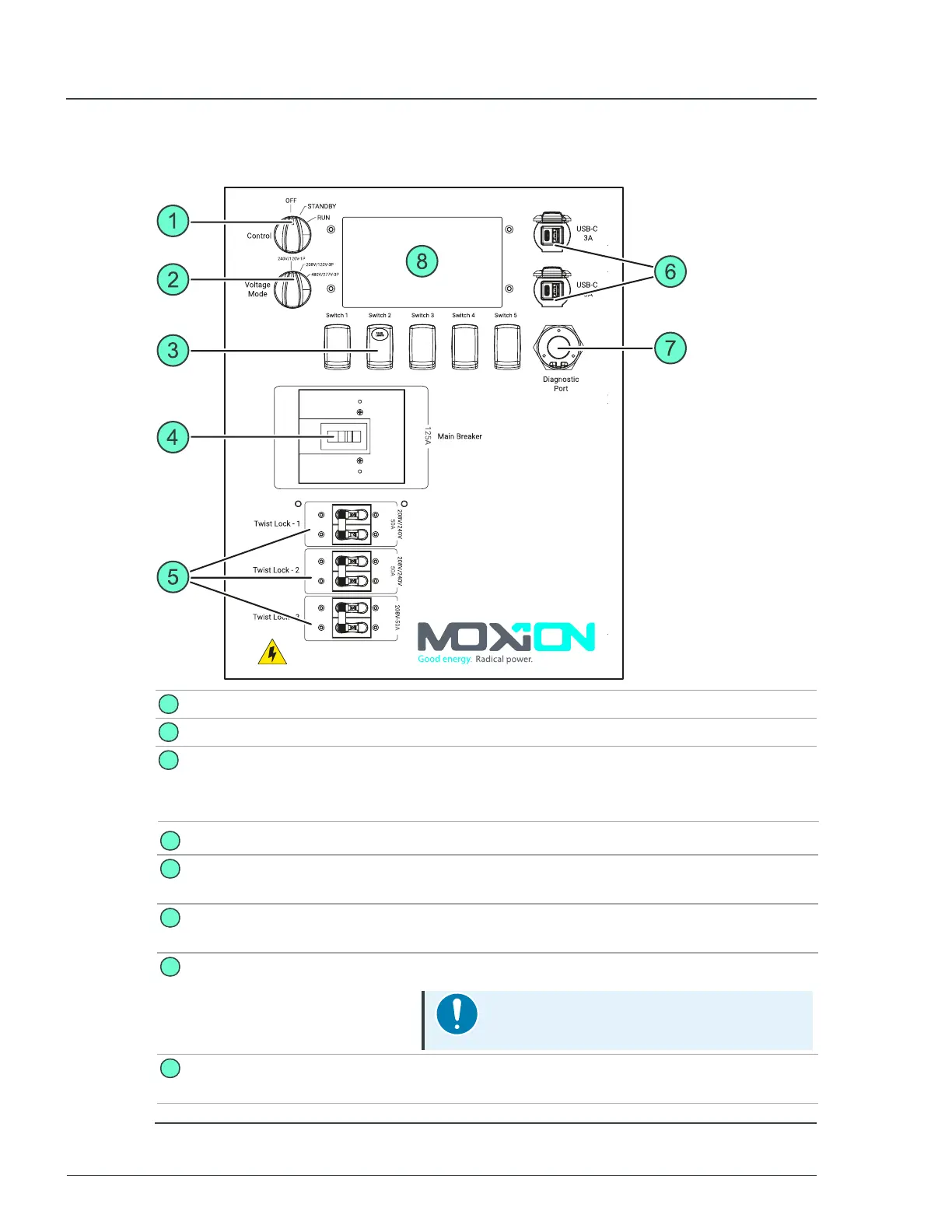
2.3.1 Main control panel
1
Control knob
Used to turn the unit on or off.
2
Voltage selection knob Used to select the voltage output requirements.
3
Panel lights switch
Used to control the panel lights at the rear of the unit. Switch 1 is
used to confirm a voltage change following a shift of the
Voltage Mode knob. Switch 4 and 5 are used for engaging
service mode.
4
Main breaker
Used to turn the main unit power on or off.
5
Twist lock breakers
Used to turn the twist-lock connections power on or
off.
6
USB-A and USB-C
connections
Used for standard USB-A and USB-C connections
(3A).
7
Diagnostic port
Used to connect diagnostic equipment.
Notice
Only for use by trained service personnel.
8
Control display
Displays the current status of the unit and available
power.
Figure 9 - Control panel details
MP75-600 - User Manual 2 Hardware description