Bolt X Quick Start Guide
60
Bolt X Quick Start GuideBolt XQuick Start Guide
Appendix 3 Bolt X panels
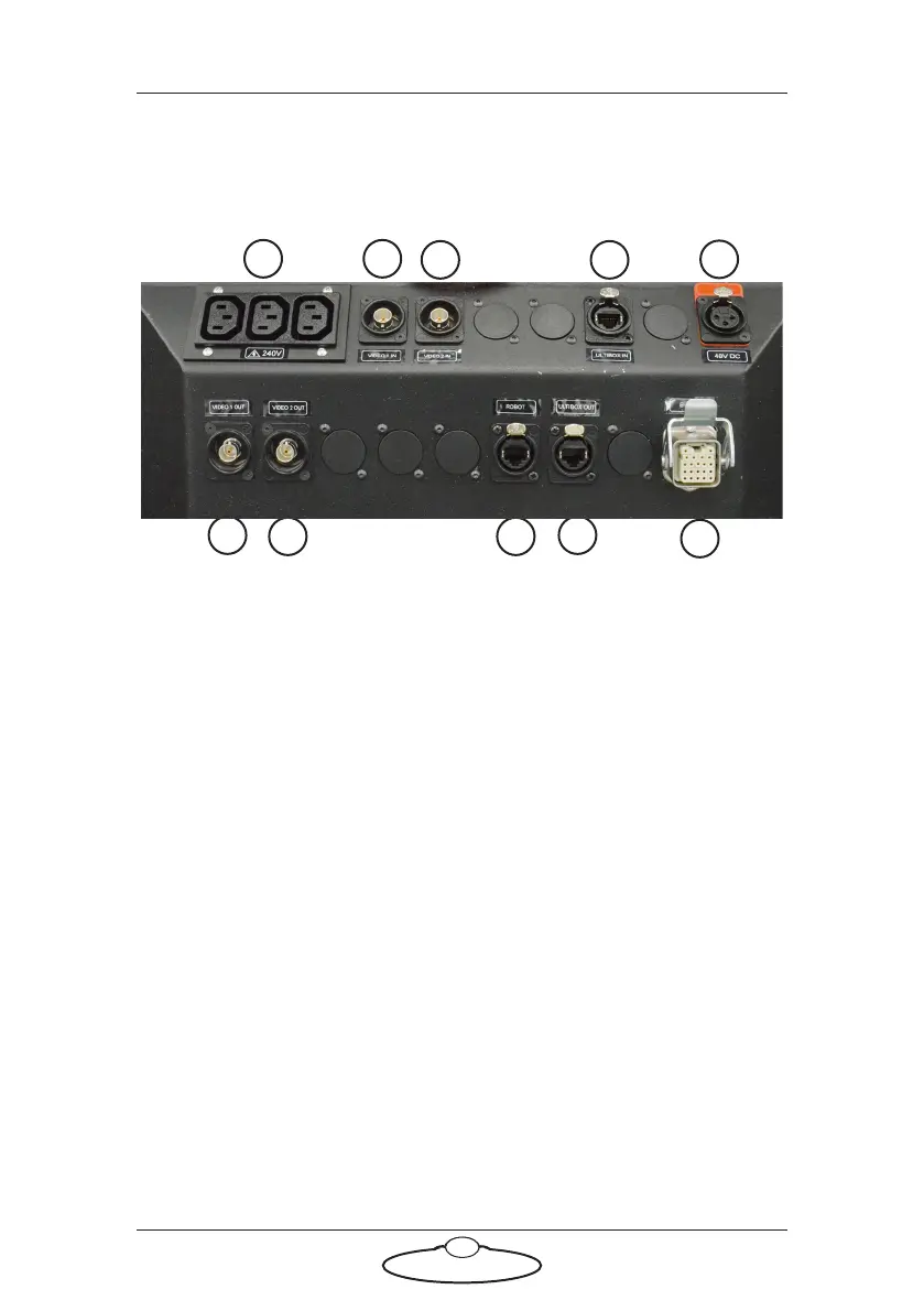
Bolt X On Track base panel connector summary
1. 240V AC output, for general use by additional devices that you want
to mount on the base.
2. VIDEO 1 IN input connector for the video 1 signal from the camera.
This has a straight-through internal connection to the VIDEO 1
OUT connector (6).
3. VIDEO 2 IN connector for the video 2 signal from the camera. This
has a straight-through connection to the VIDEO 2 OUT connector
(7).
4 and 9. ULTI ETHERNET IN and ULTI ETHERNET OUT connectors for
communications between Ulti box on the arm and Ethernet hub via
the umbilical cable.
5. 48V DC power connector. You usually use this to power the Ulti-box
(and its attachments) on the Bolt arm, by attaching a cable from this
connector to the 48V connector on the arm.
6. VIDEO 1 OUT connector for the video 1 signal from the camera.
This has a straight-through connection to the VIDEO 1 IN
connector (2).
7. VIDEO 2 OUT connector for the video 2 signal from the camera.
This has a straight-through connection to the VIDEO 2 IN
connector (3).
43
21
5
10
9
7
6
8