Bolt X Quick Start Guide
62
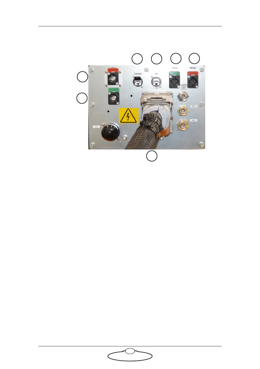
Bolt X arm panels connector summary
1. Camera connector is an Ethernet connector or communications
between the camera and the rest of the system. The connection
between these two connectors is a straight-through internal
connection through arm.
2. Ulti connector is an Ethernet connector or communications
between the Ulti box on the robot arm and the rest of the system.
You ordinarily attach this to the Ethernet connector in Bolt X base
(for Bolt X On Track).
3. VID 1 output connector for the video 1 signal from the camera. This
can be connected to the VIDEO 1 IN connector on the Bolt X base.
4. VID 2 output connector for the video 1 signal from the camera. This
can be connected to the VIDEO 2 IN connector on the Bolt X base.
5. 12 V DC input power connector. You can use this to power the
camera or other devices mounted on the camera platform.
6. 48V DC input power connector supplies 48 Volts DC output to the
Ulti box on the Bolt X arm. This has a straight-through internal
connection to the Ulti-box input connector.
65
21
4
7
3
Arm base
panel