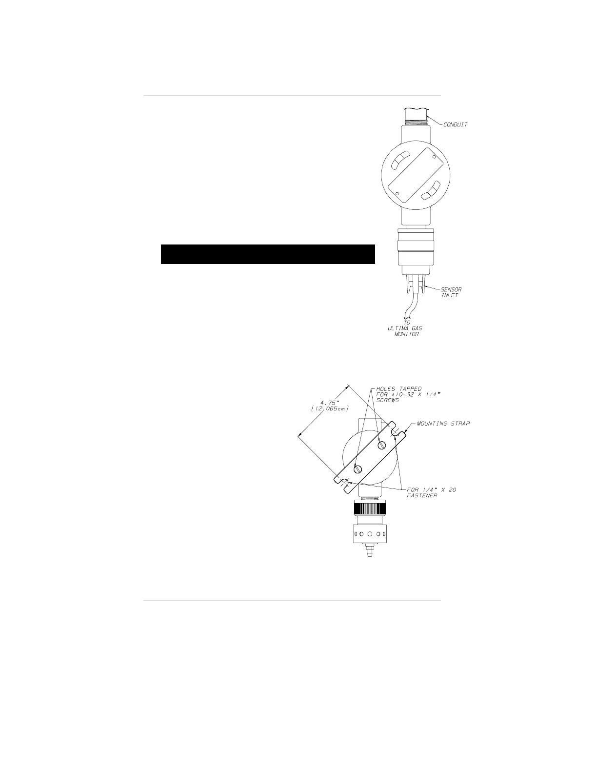
FIGURE 1-13. The sensor module wiring is routed
to the Ultima Gas Monitor which does not contain
a sensor.
Permanently connect 1/4" OD tubing to the center
post of the sensor inlet. Route this tubing to the
Ultima Gas Monitor, ensuring that there are no
kinks, leaks or other obstructions. Secure this
tubing near the monitor; it is used to deliver check
gas to the sensor module during calibration.
Electrical Connections for
Ultima Gas Monitors
"!
WARNING
Before wiring the Ultima Gas Monitor, disconnect
power source supplying the monitor; otherwise,
electrical shock could occur.
Before removing the cover of an explosion-proof
Ultima Gas Monitor, verify the surrounding area does
not contain a flammable mixture of combustible gas
and air since a source of ignition is exposed;
otherwise, an explosion may occur if a metal object
contacts the circuitry and produces sparks.
NOTE: For Ultima with Digital Output Gas
Monitors, see manual (P/N 710471) for
wiring instructions.
NOTE: For Ultima units with
internal relays,
see Appendix C.
There is no need to open the
enclosure during a typical
installation because the Ultima
Monitor design eliminates:
• Internal jumpers
(except IR versions)
• Potentiometers
• Dip switches or other
types of adjustments.
All electrical connections to the
Ultima Monitor can be made via
the factory- installed wiring
harness (FIGURES 1-14 and
Figure 1-12.
Ultima
Remote
Sensor Module
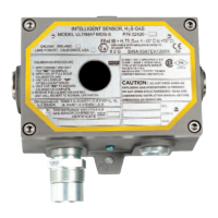
Figure 1-13.
Remote Sensor
Mounting Method
Chapter 1, Set-up
1-10