installation requirements dictate a direct connection, the Ultima
Gas Monitor can be opened and wired directly.
If you are connecting the relays to motors, fluorescent lighting or
other inductive loads, it is necessary to suppress any sparks that
may occur at the relay contact. These sparks will deteriorate or
destroy the relay contacts, rendering the relay inoperative or
useless. One way to reduce this destructive sparking is to install
a *Quencharc
®
across the contacts. This device is available from
MSA as P/N 630413.
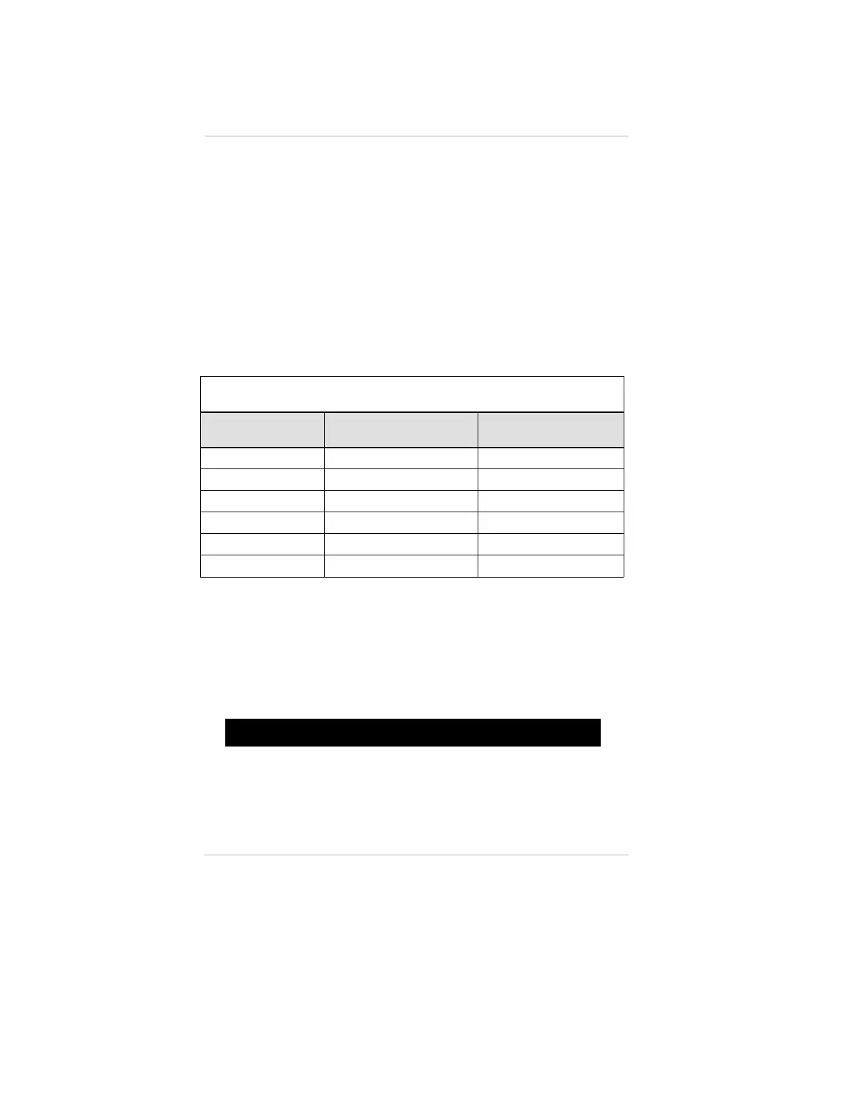
When using the wiring harness provided with the module, refer to
FIGURE C-3 for relay connection. TABLE C-4 lists wire color and
the associated relay function.
*Trademark of ITW Paktron
Table C-4. Wire Color and Associated Relay
WIRE COLOR RELAY
TERMINAL BLOCK
CONNECTIONS
B - BLUE ALARM 2
A2
O - ORANGE ALARM 2
A2
R - RED ALARM 3
A3
G - GREEN ALARM 3
A3
W - WHITE FAULT
F
K - BLACK FAULT
F
If the Wiring Harness is Not Used:
• The Ultima Gas Monitor must be disassembled for wiring
• The wiring harness must be discarded
• The following procedure must be performed:
1. Unscrew the Ultima Gas Monitor cover and set aside.
"!
WARNING
Before removing the cover of an explosion-proof Ultima Gas
Monitor, verify that the surrounding area does not contain
a flammable mixture of combustible gas and air, since a
source of ignition is exposed; otherwise, an explosion may
occur if a metal object contacts the circuitry and produces
sparks.
Appendix C, Internal Relay Option
C-8