2. Remove the two screws securing the front label assembly
(FIGURE 1-21).
3. Pull up and remove the front label assembly and the two
attached printed circuit boards.
4. Pull on the wiring plugs to disconnect the connectors on the
exposed board.
NOTE: Observe connector locations for later re-insertion.
Push the wiring plugs and wires to one side of the module.
NOTE: Do not remove the wires from the wiring
connectors.
5. Remove the two screws securing the exposed printed board in
the module.
6. Remove this printed circuit board from the module.
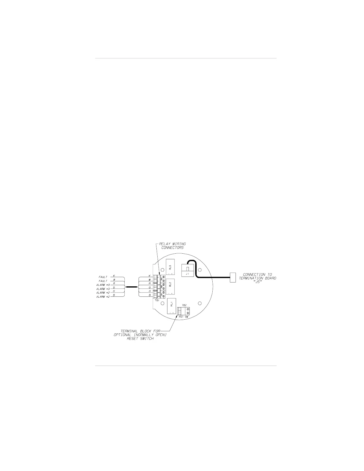
7. Locate the relay wiring harness. Remove the cable from the
terminal blocks (FIGURE C-4) and pull it through the module
opening; discard this cable.
8. Route the desired relay control cable through the module
opening and wire it to the terminal block TB1 on the circuit
board (FIGURE C-4).
• If shielded wire is used, connect shield to field wiring shield.
Figure C-4.
Relay Printed Circuit Board
Appendix C, Internal Relay Option
C-9