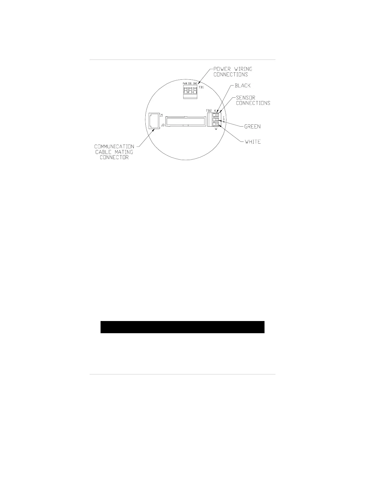
4. Remove the cable from terminal block TB2 (FIGURE 1-22)
and pull it through the conduit opening; discard this cable.
5. Route the cable through the conduit opening and wire it to
terminal block TB2 on the circuit board that remains in the
bottom of the unit. If shielded wire is used, connect the
shield to the field wiring shield.
6. Identify each conductor of the cable to enable proper
connection at the remote sensor.
7. Re-install the front label assembly and the two printed circuit
boards attached to it.
8. Re-install the two screws that secure the front label assembly
(FIGURE 1-21).
9. Screw the conduit onto the conduit opening and pull the cable
away from the unit to relieve any excess slack.
10. Re-install the cover of the Ultima Gas Monitor/Less Sensor.
"!
WARNING
Do not let the cover remain off of an explosion-proof Ultima
Gas Monitor/Less Sensor. Since a source of ignition is
exposed, an explosion may occur if a metal object contacts
the circuitry and produces sparks in an atmosphere of
combustible gas.
Figure 1-22.
Sensor Wiring Connections
Chapter 1, Set-up
1-20