Mounting the Dual module Models
1. Locate the duct to be sampled.
2. Using dimensions from FIGURE A-2, cut a rectangular hole
[8.875 by 2.7 inches (225 by 68.5 mm)] in the duct.
• The gasket on the bottom of Duct Mount Kit must sit flat
on the duct.
• If necessary, pre-drill the fastener holes.
• Do not remove the gasket paper lining on the Duct
Mount Kit at this time.
• On rounded ducts, additional gasketing may be
required for proper sealing.
3. Locate and identify all components in the Duct Mount Kit
(TABLE A-2).
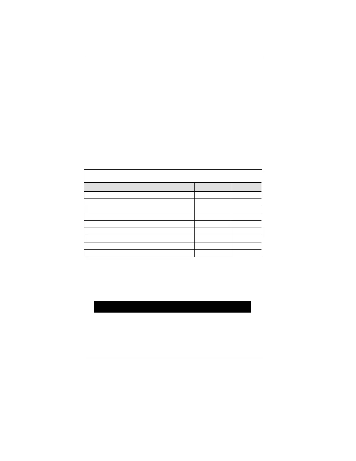
Table A-2. Dual module Duct Mount Kit Parts List
DESCRIPTION PART NUMBER FIGURE
Two Ultima Gas Monitor Spacers
710779 A-12
Ultima Gas Monitor Clamp
710778 A-13
Ultima Gas Monitor Enclosure Gasket
710770 A-6
Ultima Gas Monitor Plate
710769 A-7
Ultima Gas Monitor Duct Mount Kit Base Plate
814862 A-14
Two 1/4-inch Hex Nuts
631357
Two 1/4-inch Lock Washers
655245
Six 10-32 Screws
634054
Six #10 Lock Washers
627852
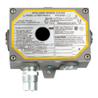
4. Locate the Remote sensor of the Ultima Gas Monitor to be
installed in the duct.
5. Unscrew the cover of the Remote sensor and set aside.
"
WARNING
Before removing the cover of an explosion-proof Remote
Sensor Ultima Gas Monitor, verify that the surrounding area
does not contain a flammable mixture of combustible gas
and air, since a source of ignition is exposed; otherwise,
an explosion may occur if a metal object contacts the circuitry
and produces sparks.
Appendix A, Optional Ultima Duct Mount Kit
A-10