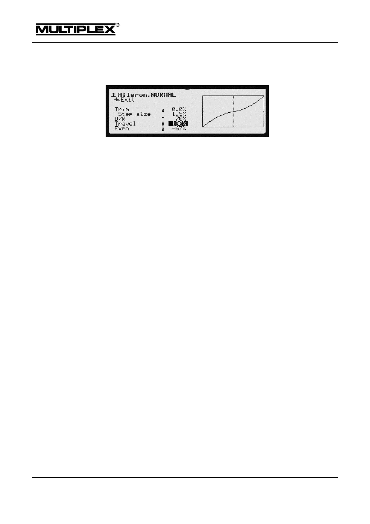
The general screen layout is identical for all menus. This example shows the
screen for the Aileron control function:
Designation of control function and active flight phase
At the top, the designation of the control function is shown followed by the
name of the activated flight phase (in the example: NORMAL).
Parameter list
On the left, all parameters for the selected control function are listed with their
set values.
o Values that can be assigned to a digi-adjuster are marked by
a horizontal dash preceding the input field (see section 6.3.1
"Allocating a set value" on page 164).
o The number next to the parameter name identifies the flight phase
(in the example: 1) to which this value applies (see section 5.3.2
"Flight phases" on page 94).
Graph
The effect of all settings is visualized in the graph on the right. The graph
immediately shows the setting changes and illustrates the behaviour of the
function. The dotted vertical line indicates the current position of the control.