Instructions
Page 73
monitoring is much safer, as it is also capable of detect-
ing faults and errors::
• Is an RF module installed?
• Is the connection between RF module and trans-
mitter in order (contact fault)?
• Is the RF module working correctly?
• Is a crystal fitted, and is it in order?
(only with HFM-4 RF module for crystals)?
• Is the transmitter aerial installed, and is it making
proper contact?
If the ROYALevo is in use as a Pupil transmitter, or in
diagnosis mode, no RF signal will be transmitted => LED
glows constantly.
9.6. The status displays
There are four different status displays available in total.
You can switch between the individual status displays at
any time (provided that you are at one of the other
status displays, i.e. not in a menu) using the „s“ or „t“
buttons, depending on the information you wish to see.
When you switch the transmitter on, the last used status
display will always appear.
Status display 1
1
2
3
4
5
6
Bars
Line 1 Status of the 3-D digi-adjustors.
Numerous set-up parameters can be assigned
to the 3-D digi-adjustors, which can then be
varied directly (è 10.2.2.).
Line 2 Current model memory with
No. of the memory (1): model name(BASIC)
Line 3 Current operating voltage of the transmitter
battery in numeric form, and also graphically
in horizontal bar form
Line 4 Version: ROYALevo 9 or ROYALevo 12
Line 5
User name (è 13.5.3.)
Line 6 Operating time of the
current model memory(è 17.1.)
Bars The 4 bars at the sides and bottom of the
screen show the current trim positions of the
4 primary control functions/sticks (è11.4.)
Status display 2 (flight phases)
1
2
3
4
5
Line 1 Status of the 3-D digi-adjustors, see above
Line 2 Current model memory, see above
Line 3 Current operating voltage, see above
Line 4 Code letter of the switch used to change
flight modes (è 18.4)
Line 5 Current flight mode with
No. (1): name (NORMAL)
Bars Current trim positions, see above
Status display 3 (Timers)
Only timers with assigned switches are displayed. Be-
hind the time the switch code letter is shown (P in the
example).
1
2
3
4
Line 1 Status of the 3-D digi-adjustors, see above
Line 2
Slot-Timer (è 17.2.)
Line 3
Sum Timer (è 17.3.)
Line 4
Interval Timer (è17.4.)
Bars Current trim positions, see above
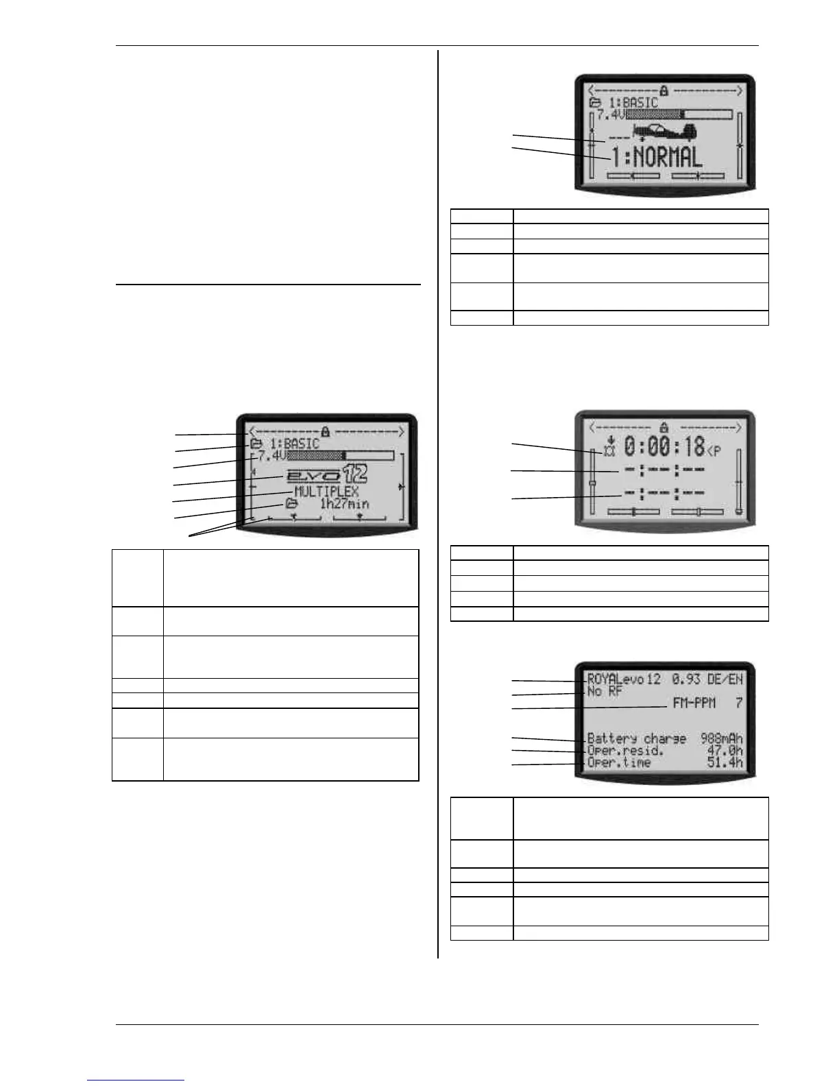
Status display 4 (system)
1
2
3
4
5
6
Line 1 Variant (ROYALevo 9 or 12),
software-version (e.g. 9/23),
language set currently loaded (e.g. DE/GB)
Line 2 with synthesizer module: channel no. freq.
else type of RF module (HFM-4) or "No RF"
Line 3 Transmission system (FM-PPM 9)
Line 4 available battery charge
Line 5 residual operating time with the residual
charge at the current power consumption
Line 6 Overall operating time of the transmitter