Example 2: 4-point 90° swashplate
Geometry -90°
Rotation +0°
Lever
0%
15.5.1. Parameter „Geometry“
I affects active model memory
Range 90 ... 150° / -91 ... -150°
Default +120°
The parameter Geometry defines the angle between
the swashplate servo Head f/b and the servos arranged
symmetrically to it, i.e. Head le and Head ri.
Attention: The angle must be entered with a negative
prefix if the servo Head f/b is at the front (in flight direc-
tion) (Ex. 2).
15.5.2. Parameter „Rotation“
I Affects active model memory
Range -100 ... +100°
negative à clockwise,
positive à anti-clockwise
Default 0°
The parameter Rotation (also termed virtual swashplate
rotation) is required,
• if the swashplate in the model is installed physically
in such a way that the servo Head f/b is not located
on the model’s centreline
• if the model rolls when a pitch-axis command is
given.
90°
140°
Flight direction
Rotation 20°
Geometry
Rotation 20°
Flight direction
15.5.3. Parameter „Lever +/-“
I affects active model memory
Range -100 ... +100%
Default 0%
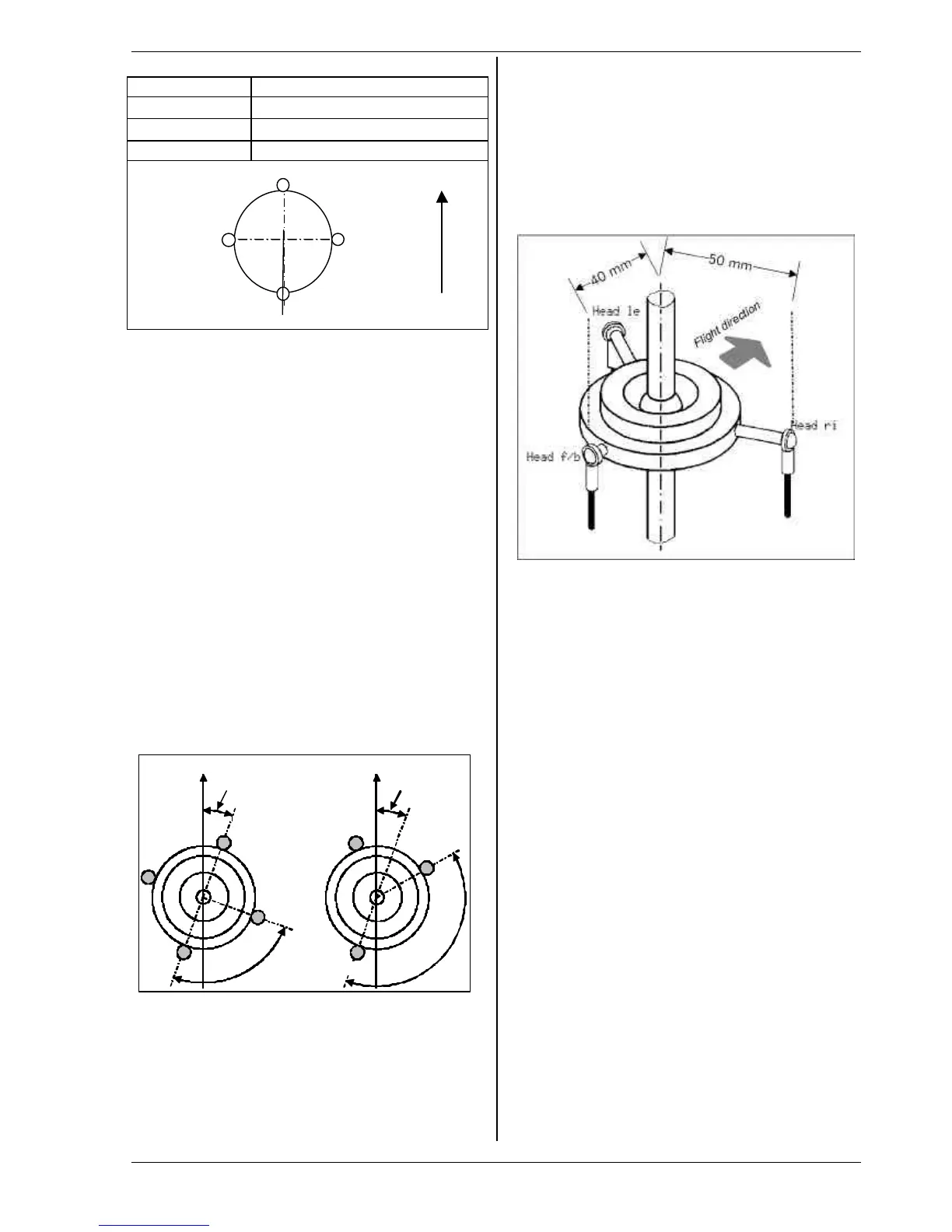
The parameter “Lever +/-“ is only needed if your model
has a 3-point swashplate whose design dictates that the
actuation points are not equi-distant from the rotor
shaft axis.
The radial spacing ratio (centre rotor shaft -> actuation
point) of the servo Head f/b is adjusted relative to the
two lateral servos Head le and Head ri in the form of a
percentage, where the lateral lever lengths are 100%.
Example:
Spacing Head f/b: 40mm
Spacing Head re (li): 50mm (=100%)
The lever for Head f/b is 20% shorter than the lateral
levers..
⇒ Correct setting: Lever +/- -20%.
' TIP:
Once you have entered the mechanical values for the
swashplate of your model into the Rotor head mixer in
the form of parameters, the next step is to calibrate the
rotor head servos carefully in the menu K Servo / Cali-
bration (è 16.1) You cannot expect the control system
to work accurately unless you calibrate the servos ex-
actly. You can check the direction of rotation of the
servos by applying collective pitch control commands. If
any servo does not run in the correct “sense” (direction),
simply reverse its direction of rotation. At the servo
calibration stage you may find it helpful to disconnect
the pushrods from the swashplate to the rotor head, as
this makes it easier to calibrate the maximum travels
(P1, P5). The control travels can be adjusted once you
have completes this stage; this is carried out in the me-
nu H Control (è 14.2.4. Aileron / Trvl., Elevator / Trvl.,
è 14.2.9. Collect. (Collective Pitch Curve).
15.5.4. Helicopters HEIM mechanics
To program a helicopter with HEIM arrangement pro-
ceed as follows:
1. Use the template "HELIccpm"
2. Assign HEAD f/b as servo 9. This servo is not used
in the model. It serves to activate the head mixing.
3. Assign Elevator (pitch axis) to the original HEAD f/b
servo.
4. In the mixer Rotor head set the parameter geome-
try to 90°. The servos HEAD le and HEAD ri will now
be controlled by Collective pitch and Aileron (Roll)
only.