Instructions
Page 83
venient method of altering values is to use the 3-D digi-
adjustor (è 10.2.2).
Step ˜˜ Activating flight phases
Once you have test-flown the model in one flight phase
(usually the Hover flight phase) and successfully
trimmed it out, with all the mixer and transmitter con-
trol values set to your satisfaction, you can consider
setting up additional flight phases (if you wish). Flight
phases enable you to optimise the model for use in
different flight situations. The first step is to activate a
new flight phase and copy the values from the first
flight phase into the newly activated phase (è 18.4.).
The transmitter control settings can now be adjusted (H
Control menu) to suit the new task, especially the col-
lective pitch curve and throttle curve. All the transmitter
control settings marked with a small number (1 ... 4) can
be adjusted separately for each flight phase (è 14.).
Step ™™ “Expert tips”
Mixer Thr.comp.Thr.comp. (Yaw/Roll/Pitch axisààThrottle)
When the collective pitch, roll, pitch-axis or yaw com-
mands are made, they may need a corresponding in-
crease in the throttle setting. The mixer Throttle com-
pensation (è 15.6.) is used for this.
Mixture mixer
Some glow plug motors feature a carburettor with vari-
able mixture facility, for which a separate servo is used
to maintain the optimum mixture at all throttle settings
(carburettor openings). One example of this is the WE-
BRA mc carburettor. The ROYALevo offers a special fea-
ture for this type of carburettor:
Assign the function Mixture to the receiver output to
which the mixture adjustment servo is to be connected,
and select 5P (è 16.2.3.) for the servo calibration. The
mixture can now be adjusted accurately in the menu K
Servo, Calibrate, Mixture (è 16.1.) , so that it suits all
positions of the throttle servo.
Mixture may not be assigned as control (è 13.3.4). If
you do so, Mixture will not be derived from the throttle
signal, but from the assigned throttle control. This
would be required if Mixture on an conventional carbu-
rettor is controlled by an auxiliary channel.
12.4. Model templates in detail
The following sections contain detailed descriptions of
all the model templates which are present in your
ROYALevo.
In each template description you will first learn the
types of model for which the template is suitable.
The first section (12.x.1.) tells you which transmitter
controls and switches are assigned. The drawing also
shows how the various switches and transmitter con-
trols must be set to ensure that the model can be
switched on in as safe a state as possible.
The second section (12.x.2) includes a drawing showing
the receiver outputs to which the servos (speed control-
ler, gyro) have to be connected. This sequence can be
changed in any way you wish (è 16.2.).
The third section contains (12.x.3.) notes on how to
adjust the model to meet your specific needs and pref-
erences.
!!
The next two steps must always be carried out
when you start programming a new model.
a. Check the stick functions (aileron/elevator/rudder); if
necessary select a different mode (è 13.3.1.)
L, Assignment, Mode
b. Check the direction of servo rotation for all functions,
if necessary reverse the directions (REVERSE)
K, Calibrate, select servo, Parameter REV/CLR
12.5. Template: BASIC
suitable for:
simple power models
models with one or two aileron servos,
models with spoilers (landing flaps or airbrakes)
Typical models:
Lupo, PiCO-CUB, Movie Star (fig. 12.4.2.), Twin-Star,
Big Lift
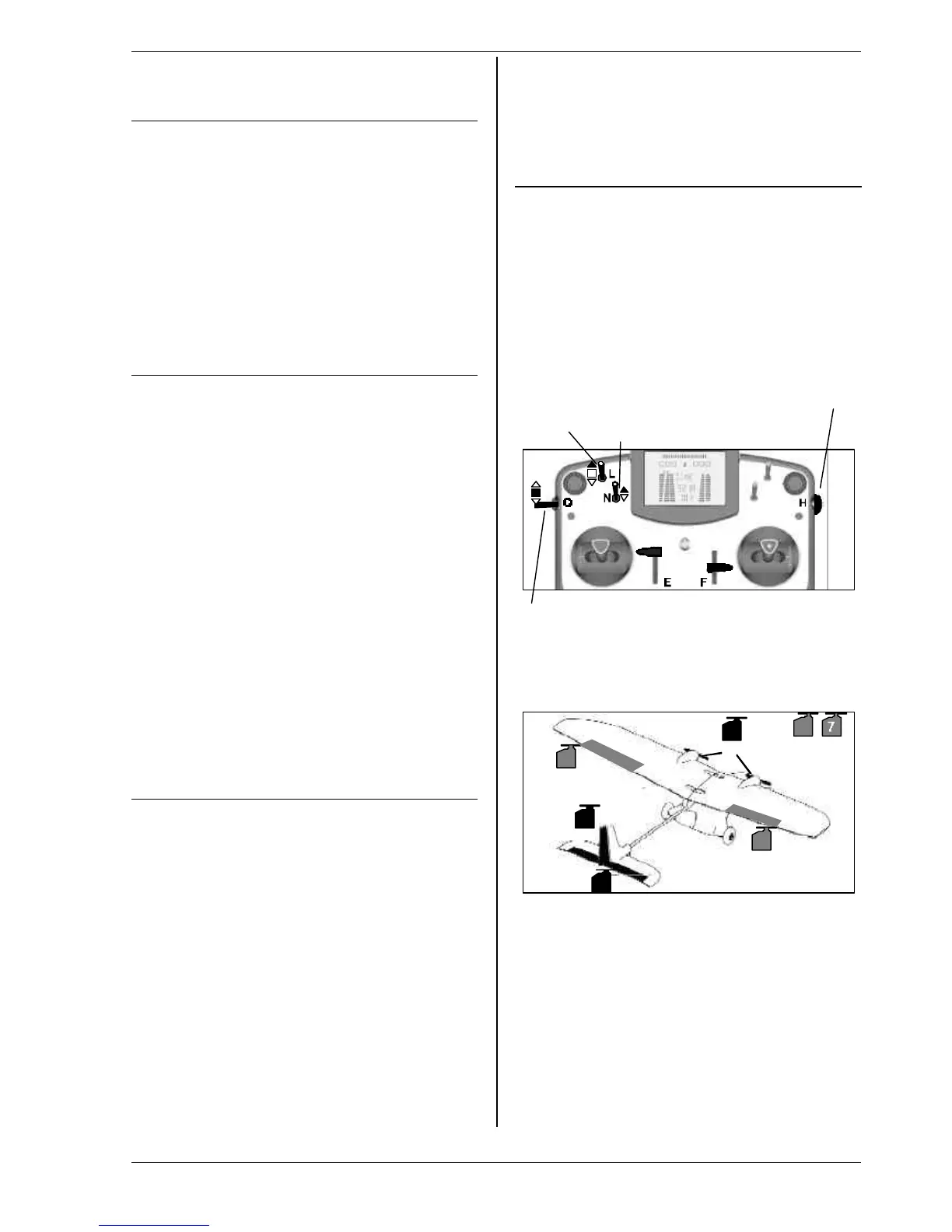
12.5.1. Assigned transmitter controls and switches
Assignment used: POWER
not used: Flap (F)
A : Sum timer ´ controlled by throttle (‡)
Dual-Rates Combi-Switch Throttle-cut
A/E/R (button)
OFF OFF
Phase 1-3
1: NORMAL
12.5.2. Assigned servos / receiver outputs
To ensure that the template can be used for as many
model types as possible, more servos can be assigned
than are required for the model shown in the drawing.
1
5
4
3
6
2
Aileron
Throttle
Aileron
Rudder
Spoiler
ELEVATR+
12.5.3. Fine-tuning
!!
Steps a. and b. (see left)
c. Activate throttle - elevator mixer
select G, ELEVATR+, input Thr -Tr ,
set 10% down elevator
For fine adjustment in flight assign the value to the
3-D digi-adjustor (è 10.2.2.).