ROYAL evo
Page 104
of the curve. The shape of the curve is unchanged. This
is the same as with the standard trim option.
Use servo trim TRM only to correct deviations in a
servo’s neutral position which you discover when set-
ting up the model. Don’t use it to trim a new model: the
mechanical linkage should always be adjusted as accu-
rately as possible.
16.1.2. Parameter „P1 … P5“
Adjusting the servo calibration points (parameters “P1 ...
P5”) can be useful in several ways. In detail these are:
• Defining the maximum working range of the servo
The servo travels never exceed the values (servo travels)
you set here.
(guards against the servo being stalled mechanically)
• Setting symmetrical control surface travels
• Adjusting the travels of several servos to match
each other.
This avoids the risk of mutual stalling, i.e. when two (or
more) servos are actuating the same control surface.
• Compensating for mechanical differences in the
control surface linkage
For example, if the flaps of a multi-flap wing do not mo-
ve through exactly the same deflections, the travels can
be matched to each other by adjusting the intermediate
points P2 and P4.
Careful calibration is important, especially in the case of
servos to which a mixer has been assigned.
! Note:
Servo calibration should only be used for fine adjust-
ment; it is not a remedy for an inaccurate mechanical
linkage. Always set up the mechanical system accurately
as the first step. On no account reduce the maximum
servo travels (P1 and P5) by more than about 10 - 20%,
otherwise you effectively reduce the maximum power
of the servo, and the effect of any lost motion in the
servo gearbox is amplified.
This is the procedure for calibrating a servo:
1. Servos, controlled by basic (non-mixed) functions
(Aileron, Elevator, Rudder, Undercarriage, ...):
First ensure that the direction of servo rotation
(control surface travel) is in the correct “sense”. If
necessary change the sense of rotation in the pa-
rameter REV/TRM (è 16.1.1.). If you subsequently
reverse the servo, you will need to repeat the
calibration procedure.
Servos, controlled by mixers
(AILERON+, DELTA, V-TAIL, ...):
If you have assigned a mixer to the servos the direc-
tion of servo rotation is not relevant. The correct di-
rection for the control surface travel is set in the mi-
xer itself.
2. Select the value of one of the points (P1 to P5). Now
press the digi-adjustor assignment button <
F
>.
The servo automatically takes up the position of the
selected calibration point and remains there. With
one hand you can now easily and conveniently
measure and check the travel (ruler, calliper); the
other hand remains free, and can be used to adjust
the value using the UP/DOWN buttons s / t or
one of the two 3-D digi-adjustors.
If the deflection is correct, press the digi-adjustor
assignment button < F > again. The servo moves
to the position given by the current position of the
corresponding control.
The number of variable servo calibration points (min. 2,
max. 5) varies according to the setting you selected
under Servo Assignment (è 16.2).
' TIP: Vertical dotted line for orientation
The vertical dotted line always shows the current servo
position, to help you understand “where you are”. Press-
ing the digi-adjustor assignment button < F >(*), or
moving the transmitter control associated with the
servo or servos, releases the servo again at the selected
calibration point. The servo takes up the position corre-
sponding to the position of the associated transmitter
control(s).
16.2. Sub-Menu „Assignment“
I affects the active model memory
free assignment of servos
assignments in the model templates for MULTI-
PLEX or other standards
all 9 (or 12) servos are shown in the list
As with the MULTIPLEX PROFI mc 3000 and 4000 series
of radio control systems, the ROYALevo offers the facility
to define the sequence, or order, of the receiver outputs
- with no restrictions. Compared to radio control sys-
tems with a fixed receiver output sequence this pro-
vides the advantage that, for example, the signal for a
second aileron servo (usually generated on the “high”
channels, e.g. channel 5) can be assigned to any chan-
nel you wish. This makes it possible to use two aileron
servos even with a small 4-channel receiver.
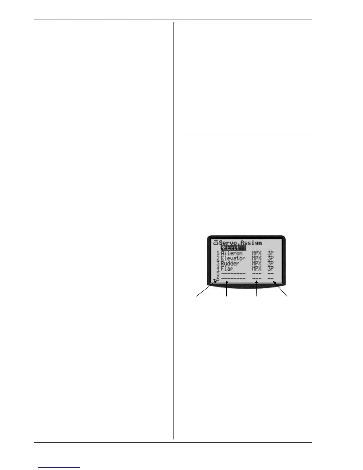
Col. 1 Col. 2 Col. 3 Col. 4
Servo-No. Control Pulse Number of
or Mixer format points
Details see tabele on the right-hand side.
This is the assignment procedure:
1. Select a servo,
then press the 3D digi-adjustor
2. Select function (control or mixer),
then press the 3D digi-adjustor
3. Select pulse format (or leave it as it is),
then press the 3D digi-adjustor
4. Select the number of calibration points,
then press the 3D digi-adjustor
The cursor jumps back to the selected servo number.
Assignment is finished for this servo.
This is the procedure to cancel assignments:
1. Select a servo,
then press the 3D digi-adjustor
2. Press the REV/CLR button,
then press the 3D digi-adjustor