Instructions
Page 111
19.4. Using MULTInaut IV
Models equipped with the MULTInaut IV receiver unit
can be operated with the ROYALevo.
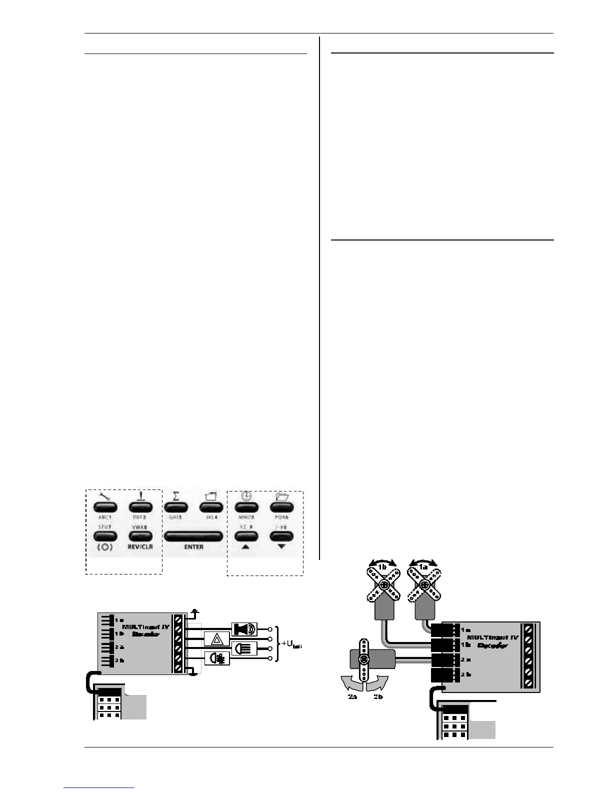
The buttons of the ROYALevo are used to control the
MULTInaut functions. No additional switches are re-
quired. All you need are the receiver units in the model.
4 buttons in two groups are assigned to each MUL-
TInaut channel and control the connect lamps, servos,
etc.
The effect of a key-press depends from the selected
operating mode. The following possibilities exist:
1. Left-hand sketch for Servo 5 = M.naut 1
Switching loads (e.g. lamps, horns, ...)
Each key-press changes (toggles) the status of the
load. (OFF à ON resp. ON àOFF)
2. Right-hand sketch Servo 6 = M.naut 2
a. Move servos between two positions
(e.g. undercarriage, tow hook release, ...)
Each key-press moves the servo (A or B) from one
position to the other.
(right à left resp. left à right)
b. Move the servo continuously (quasi-
proportional)
(e.g. mixture)
As long as the key is pressed the servo (C) moves
into one direction until it reaches its end-point.
The full travel is split in 32 steps and takes approx.
4 sec.. A short hit on the key initiates a step of
approx. 3°.
This is how to activate MULTInaut
1. Assign M.naut 1 or 2 to the receiver output where
the decoder unit is connected to.
2. Back to one of the four status displays press the
ENTER button for more than 3 sec. to activate the
button groups for MULTInaut operation.
Message in the display:
MUTLINAUT keyboard active
3. Press the ENTER button for more than 3 sec. again
to end the MULTInaut operating mode.
19.5. Diagnosis lead
You can connect the transmitter to the receiver directly
using a diagnosis lead, in which case the transmitter
does not generate an RF signal. This can be very useful
for making adjustments, checking travels etc.
This is the procedure:
1. Connect the appropriate diagnosis lead to the
multi-function socket on the back of the transmit-
ter, and to the model’s receiving system
2. First switch the transmitter on (RF remains off)
3. Switch the receiving system on
Different diagnosis leads must be used according to the
receiving system in the model:
Diagnosis lead
for MULTIPLEX switch leads with charge socket # 8 5105
for the „EinStein“ # 8 5162
19.6. PC interface
The multi-function socket on the back panel of the
ROYALevo provides the functions Charge, Teacher/Pupil
(Trainer) and diagnosis mode, and also works as a serial
interface for connection to a PC. Two functions are pos-
sible via this interface:
• Access to transmitter data
• Use of transmitter to control model flying simula-
tors
19.6.1. Accessing transmitter data
Data exchange between transmitter and PC offers the
following possibilities:
• Back-up model memory data on the PC
• Load new software into the transmitter
The latter point provides a unique feature: in conjunc-
tion with the Internet this opens up entirely new meth-
ods of updating the transmitter software, or download-
ing new screen languages.
The software (# 85 5321) and the matching connecting
lead (# 8 5157) required for these functions are available
as optional accessories.
19.6.2. Flight simulator operation
Many manufacturers of flight simulators offer interface
cables with which MULTIPLEX transmitters can be con-
nected directly to the PC. The MULTIPLEX interface ca-
ble is not designed for use with simulators.
If you have queries regarding this application, please
contact the manufacturer of the simulator.
1 a
1 b
2 a
2 b
GND