ROYAL evo
Page 64
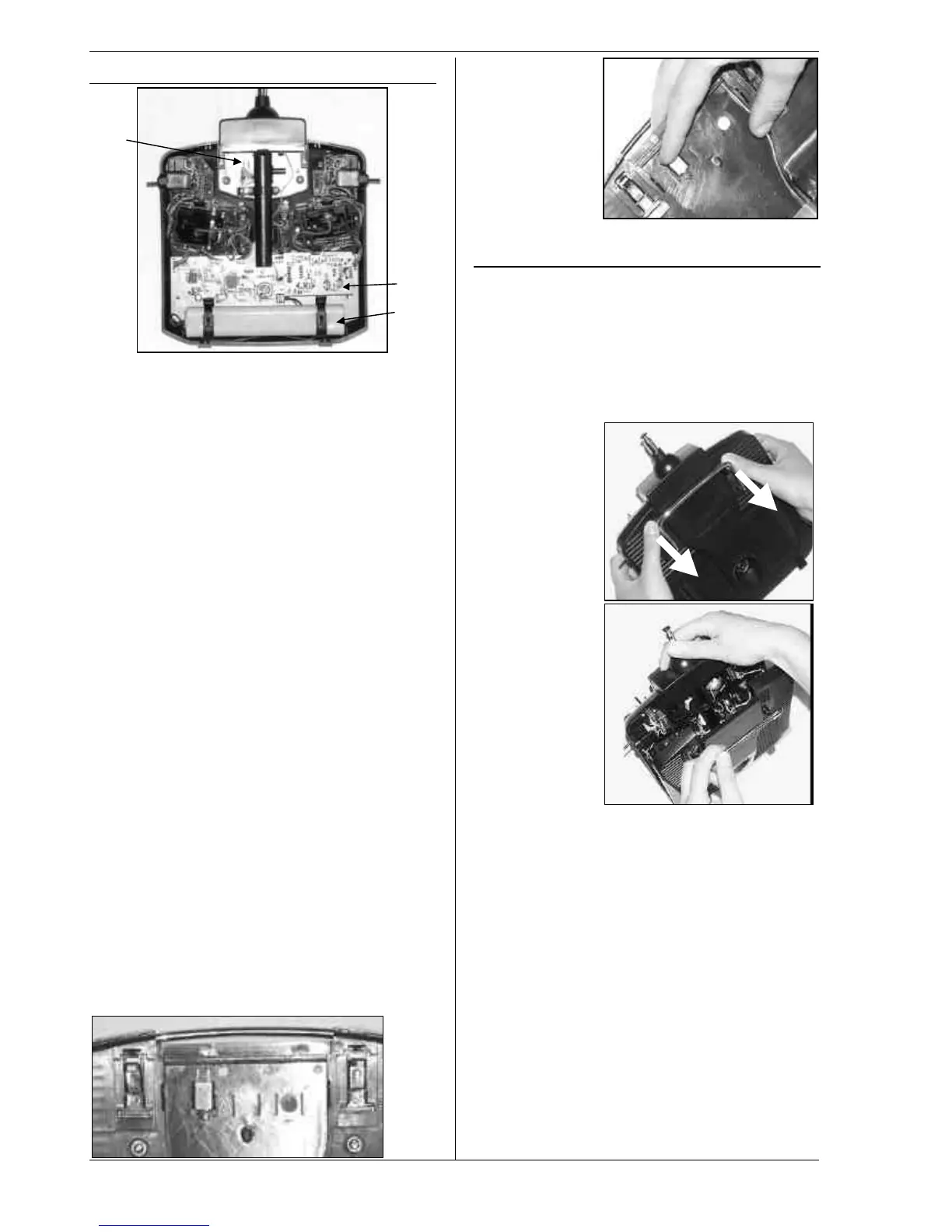
7.3. Inside the transmitter
The rechargeable transmitter battery • is installed as
standard. It consists of 6 environmentally friendly high-
capacity AA-size NiMH cells (Nickel-Metal-Hydride). For
safety reasons the individual cells are spot-welded to
ensure constant contact, and the pack is protected by a
heat-shrink sleeve.
! The transmitter battery is fitted with a special
thermo-fuse which protects the battery and -
above all - the transmitter from short-circuit, re-
verse polarity and excessive currents. The trans-
mitter itself does not feature a separate fuse, and
for this reason the battery may only be replaced
by a genuine MPX transmitter battery pack de-
signed exclusively for this transmitter. It is also
very important to observe the instructions for
charging the transmitter battery (
èè 8.).
RF module
‚ (Radio Frequency module). The RF mod-
ule is simply plugged into the main circuit board, and
can easily be changed if you wish to switch to a differ-
ent frequency band (è 7.4.3.). Two different RF mod-
ules can be used in the ROYALevo:
HFM-4:
A simple, low-cost RF module with plug-in crystals for
selecting the channel (transmission frequency). Use only
genuine MULTIPLEX transmitter crystals! The optional
“Channel-Check” power-on guard module can be fitted
at any time.
HFM-S:
A modern synthesizer RF module which allows you to
select the channel (i.e. transmission frequency) by soft-
ware. An optional scanner with power-on guard can be
fitted at any time.
The TORX ® screwdriver ƒ (size T6), which you will find
in a clip below the aerial well, close to the screen, is
used for tasks such as swivelling the stick units, and for
installing the auxiliary switches in wells “K” and “P”.
On the inside of the transmitter back panel there are
crystal holders for 3 spare crystals.
! Don’t lever the crystals out! Slide them out!
Slide!
7.4. Mechanical details
7.4.1. Opening and closing the transmitter case
! Be sure to switch the transmitter OFF before
opening it (short-circuit hazard)!
Opening the transmitter case:
1. Hold the transmitter in both hands and push the
sliding latches on the back panel downwards with
your thumbs (towards “OPEN”) (Fig. 1).
Carefully lift off the back panel of the case (Fig. 2).
Fig. 1
Fig. 2
Closing the case:
1. Carefully position the back panel on the rear edge
of the case, holding it at an angle as shown, and
check that both retainer lugs are correctly engaged
(arrow) (Fig. 3).
2. Carefully close the case back (Fig. 4).
! Check that no cables are snagged, and that the
transmitter aerial has not slipped out of its guide
sleeve. It should be possible to fit the case back eas-
ily and without forcing.
3. Push the sliding latches up as far as they will go, in
the opposite direction to “OPEN”.
•