Instructions
Page 103
Column 1
(above input)
Shows the mixer option assigned
to the mixer input in the form of a
symbol (è 13.2.3)
Column 2+3 Show the type and effect of the
mixer values.
Column 4 Indicates whether the mixer input
can be switched off; if so, which
switch is used, and the current
switch status:
Asterisk * mixer input = ON
Arrow shows ON position of
switch (if input is OFF)
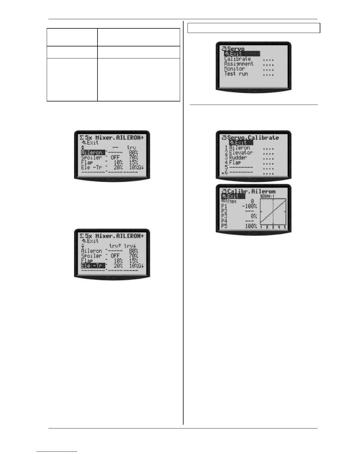
Example:
The input (transmitter control) Aileron (primary input)
affects the aileron servo(s) symmetrically relative to the
servo centre, with a travel setting of 80%.
Example:
The input (transmitter control) Ele -Tr (Elevator, no trim)
affects the aileron servo(s) asymmetrically relative to the
servo centre (snap-flap). The travel setting is 30% in one
direction, 20% in the other. The mixer input can be
switched off using switch G. The current switch status is
ON (asterisk *), i.e. the input is activated.
16. Main menu „Servo“ KK
I affects active model memory
16.1. Sub-menu „Calibrate“
In “Calibrate” you can adjust the travels, centres and - if
required - intermediate points for all servos, to ensure
that the servos move identically and evenly, and reach
the required end travels.
All changes to the parameters REV/TRM and the servo
calibration points P1 ... P5 are shown immediately in the
graph, making it easy to understand the effect of the
changes you make.
Line 1 always displays the name (function) of the servo.
The channel number (receiver output) of the selected
servo is shown above the graph.
Below the graph (X-axis) the numbers 1 ... 5 correspond
to the servo calibration points P1 ... P5.
16.1.1. Parameter „REV/TRM“
The first parameter REV/TRM has two functions:
1. Servo reverse (REV) changes the
direction of rotation
2. Servo trim (TRM)
Servo reverse REV
To reverse the direction of servo rotation simply select
the parameter value and press the REV/CLR-button:
⇒ the curve is “reversed”
⇒ the prefix changes
(only if the value of the parameter TRM ≠ 0)
Servo trim TRM
Servo trim is used to compensate for variations from the
nominal neutral position of one control surface. A cor-
rection may be necessary with servos, for example,
which do not feature adequate temperature compensa-
tion, and whose neutral position tends to vary.
The value for TRM operates on the standard trim princi-
ple, i.e. the set trim value works as an offset on all cali-
bration points P1 ... P5, thereby effecting a parallel shift