ROYAL evo
Page 82
Step •• Setting up and testing the gyro
The model templates are designed to reflect the fact
that most modellers nowadays use a standard gyro
system (normal/damping or heading lock) whose gain
(sensitivity) can be adjusted from the transmitter using
a separate channel.
In the ROYALevo’s two model templates HELImech and
HELIccpm the default setting is the simplest method of
gyro gain control: the gyro mode Transmitter control
(è 15.3). In this mode gyro gain is adjusted manually
using the transmitter control Gyro (slider E). If you wish
to assign a different transmitter control, this can be
done in the menu L Setup, Assignment (è 13.3).
The first step is to establish the position of the transmit-
ter control which corresponds to maximum gyro gain.
This is done by moving the appropriate transmitter
control to one end-point, and moving the model a-
round its vertical axis. At maximum gain the corrective
travel of the tail rotor will be at a maximum. If maximum
gyro gain is obtained at the opposite position of the
transmitter control, you need to reverse the “direction
of rotation” of the gyro channel (è 16.1.1).
The optimum gain setting for the gyro has to be estab-
lished with the model in flight. For the first few flights
we recommend a gain setting of around 50%. During
the first few test-flights increase gyro gain gradually
until the tail begins to oscillate. Now reduce the gain to
the point where the oscillation can just no longer be
detected. This is the optimum gyro gain setting.
! Caution!
Before you fly the model it is essential to ensure that the
gyro is working correctly, i.e. that it is set up to counter-
act any rotational movement. If the gyro is set up incor-
rectly, it will amplify any tendency to swing, and the
helicopter will be uncontrollable. Please read the in-
structions supplied by the gyro manufacturer.
In addition to gain adjustment from the transmitter
control (gyro mode Transmitter control) the ROYALevo
offers further facilities for optimising gyro gain sepa-
rately for each flight phase.
(gyro modes Damping, Heading è 15.3.).
Step –– Getting to know the method of working of
the throttle limiter and direct throttle
Throttle limiter
We strongly recommend the use of the throttle limiter.
This is slider F in the model templates.
' TIP: Changing the assignment
If you wish to re-assign the throttle limiter (and also the
idle setting: idle forward/back) you can change it at any
time. (è 13.3. L Setup, Assignment)
When the throttle limiter is at the idle position, the mo-
tor runs at a rotational speed dictated by the parameter
Min. (è 14.2.10), For safety reasons the collective pitch
stick has no influence on throttle at this position. The
motor can now be started safely. Fine adjustment of the
motor’s idle speed is available at any time quickly and
simply using the trim associated with the collective
pitch stick. Set the model on the ground at the take-off
patch and move a safe distance away, then check that
the collective pitch stick is at collective pitch minimum
before slowly moving the throttle limiter to the full-
throttle position. The motor will now accelerate to the
throttle value corresponding to collective pitch mini-
mum (throttle curve P1 è 14.2.10.). The throttle curve is
now “released”, and the model is ready to fly. Throttle is
controlled by collective pitch via the throttle curve you
have already set.
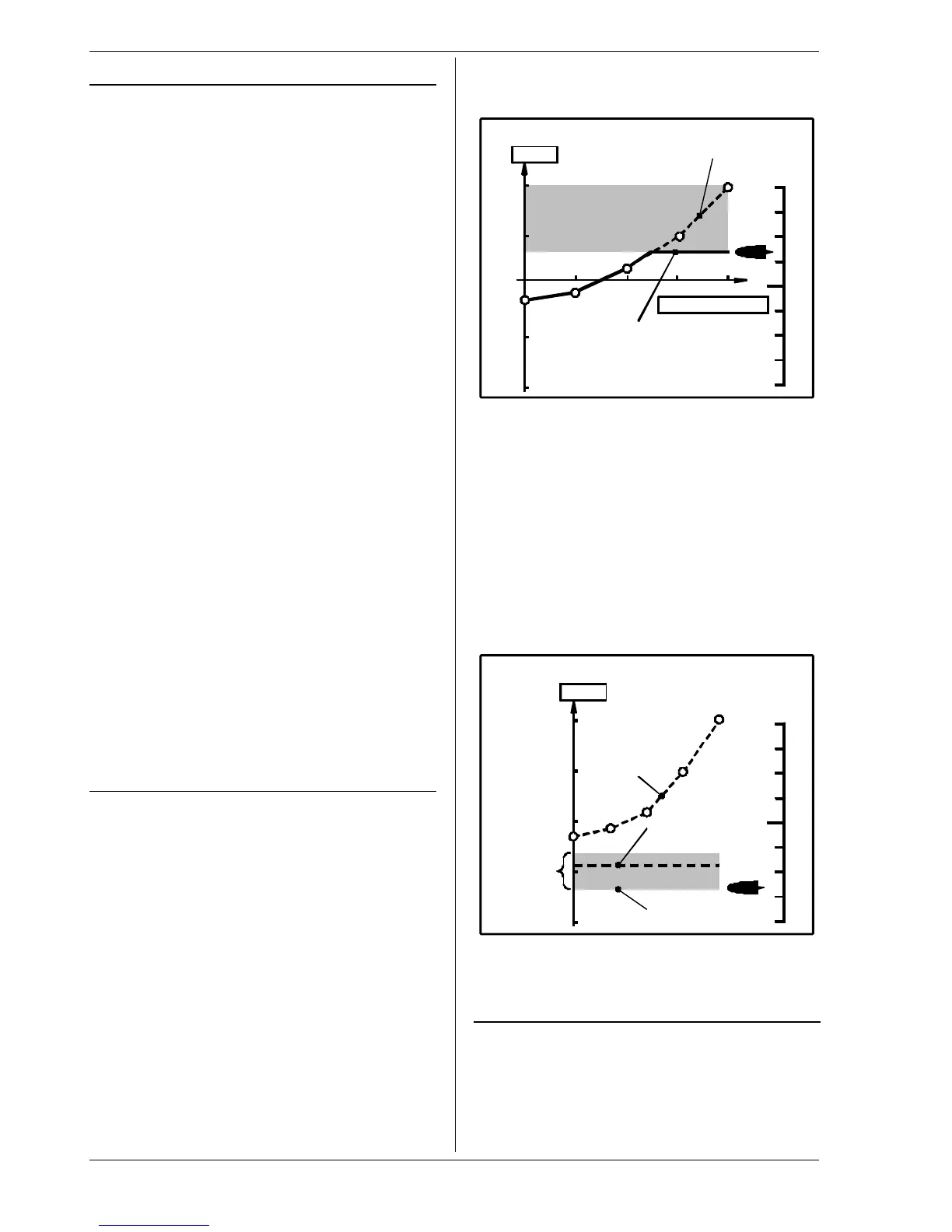
max.
+100%
+50%
0%
min.
Throttle
Collective pitch stick
Range blocked by
throttle limiter
Helicopter throttle curve
Programmed
throttle curve
Actual course
of throttle
Throttle limiter
Direct Throttle
For testing and adjusting the motor the ROYALevo of-
fers the Direct Throttle facility. Direct throttle means
that the motor can be controlled from idle to full-
throttle using the throttle limiter, independently of the
collective pitch stick. For example, the motor can be set
to full-throttle on the ground for testing, and can be
loaded with negative blade pitch (minimum collective
pitch) (keep a safe distance!). The Combi-Switch is used
to activate the Direct Throttle function (è 13.3.5.).
! Caution
Ensure that the throttle limiter is at idle before you acti-
vate Direct Throttle, otherwise the motor may run up to
full-throttle immediately!
+100%
+50%
0%
Throttle
Helicopter throttle
Throttle limiter
Trim
range
(20%)
Idle
(Throttle min. + Trim)
Throttle curve
Throttle min.
Note:
Use the Throttle-Cut to stop the motor not the throttle
trim. (è 13.3.5).
Step —— Before test-flying
Your newly created model is now ready to fly. Before
you operate the model for the first time be sure to test
all the working systems carefully.
You will probably need to fine-tune various aspects of
the control system, especially relating to mixers and
transmitter control settings, and this is done during the
test-flying process. Don’t be tempted to make changes
in a menu while the model is in the air. The safe, con-