8-8
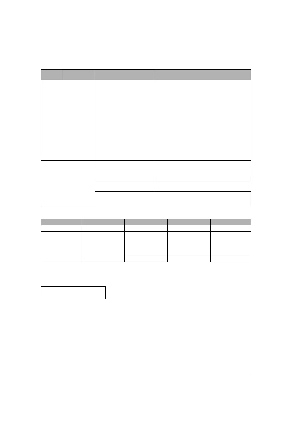
Address
Confirmed
status
Setting content and value Description
7
th
word Error
parameter No.
Note4)
K1: Unit No. setting error
K2: Baud rate setting error
K3: Character bit setting error
K4: Parity setting error
K5: Stop bit length setting
error
K6: RS/CS valid/invalid
setting error
K7: Send waiting time setting
error
K8: Header STX setting error
K9: Terminator setting error
K10: Terminator judgement
time setting error
K11: Initialize modem setting
error
The bit 8 of the setting error code (communication
condition setting value error) becomes “1” when the
values that are out of range were specified. This
area is the area to discriminate which setting value
is abnormal.
Note6)
Shows the status of the
modem initialization process.
H0: Not processed -
H100: During initialization Mode LED flashes.
H200: Initialization succeeded Modem initialization succeeded. The operation
mode automatically returns to the previous mode.
8
th
word Modem
initialization
status
H2FF: Initialization failed Modem initialization failed.
The operation mode automatically returns to the
previous mode.
Each action of each operation mode when detecting reception
Error code ER-LED XA (C) X6 (7)
Computer link Setting Lights Invalid Invalid
General-purpose
serial
communication
Setting Lights Valid (Off to On) Valid (takes
affect right after
execution of
F161 (MRCV))
PC(PLC) link Setting
Note)
Invalid Invalid Invalid
Note) The error LED in the PC(PLC) link mode goes off when the link was establised, and lights when an
error occurs in the PC(PLC) link.
Operation when detecting setting error
Sets the setting error code.
XB (D) turns on.