8-9
Note1)
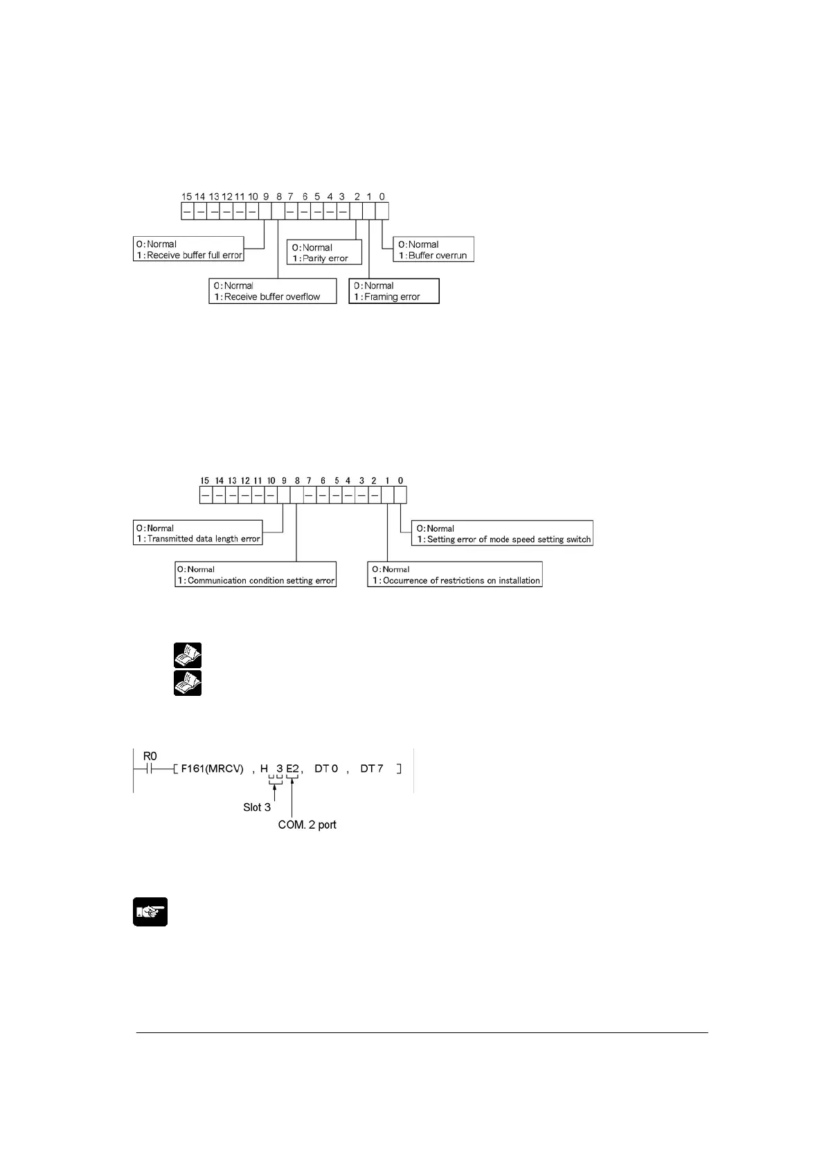
-: Fixed with 0.
Note1-1) Errors may not be detected depending on received data organization.
(Example: only when stop bit differs)
Note1-2) When a buffer error occurs, MCU stops receiving data. Turn on YE (F) and reset the
channle to clear the errror.
Note2) No. of counts is a ring counter (without code).
Note3)
-: Fixed with 0.
Note4) It is K0 when no parameter error occurs.
Note5)
Reference: <1.3 Restriction on Units Combination>
Note6)
Reference: <8.2 Setting Communication Conditions and Monitoring>
Example of monitor program
When monitoring the status of the COM. 2 port in the slot 3
When R0 turns on, the status of the COM.2 port in the slot 3 is stored in DT1 to DT7 of the receive buffer
starting from DT0.
Note:
• The No. of bytes “K14” for valid received data is stored in the first address of receive buffer.
• Receive buffer should be assured for 8 words.