6-14 CABLE TERMINATION
NWD-107460-02E Installation
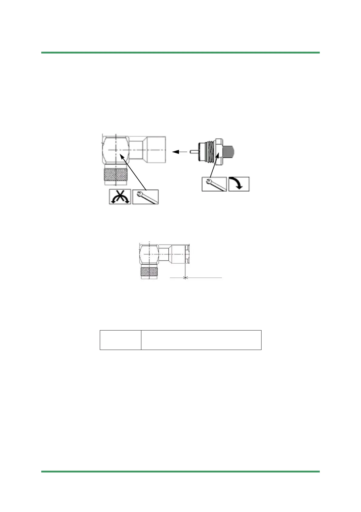
6 Connector assembly
(1) The cable center conductor must be straight and aligned with the connector
inner contact. Insert the cable into the connector body until stopped; the center
conductor must be inserted into the connector inner contact fingers. Tighten
the connection to the torque value of 60 to 80 lb-in (6.8 to 9.0 N·m).
(2) The gap of the connector body and clamp nut is confirmed.
Gap: 0 to 0.5 mm
Notes
1 When inserting, do not put the chip which is braided wire inside the
central conductor and the connector body.
2 Do not turn connector body, turn clamp nut attachment.
Tools
• spanner (16 mm)
• torque spanner (15 mm)
Submission Prohibited
NEC Internal Use Only
 Loading...