“Confidential, Do Not Duplicate without written authorization from NEC.”
8-23
CIRCUIT DESCRIPTION
D2 Configuration
D12 FPGA DONE
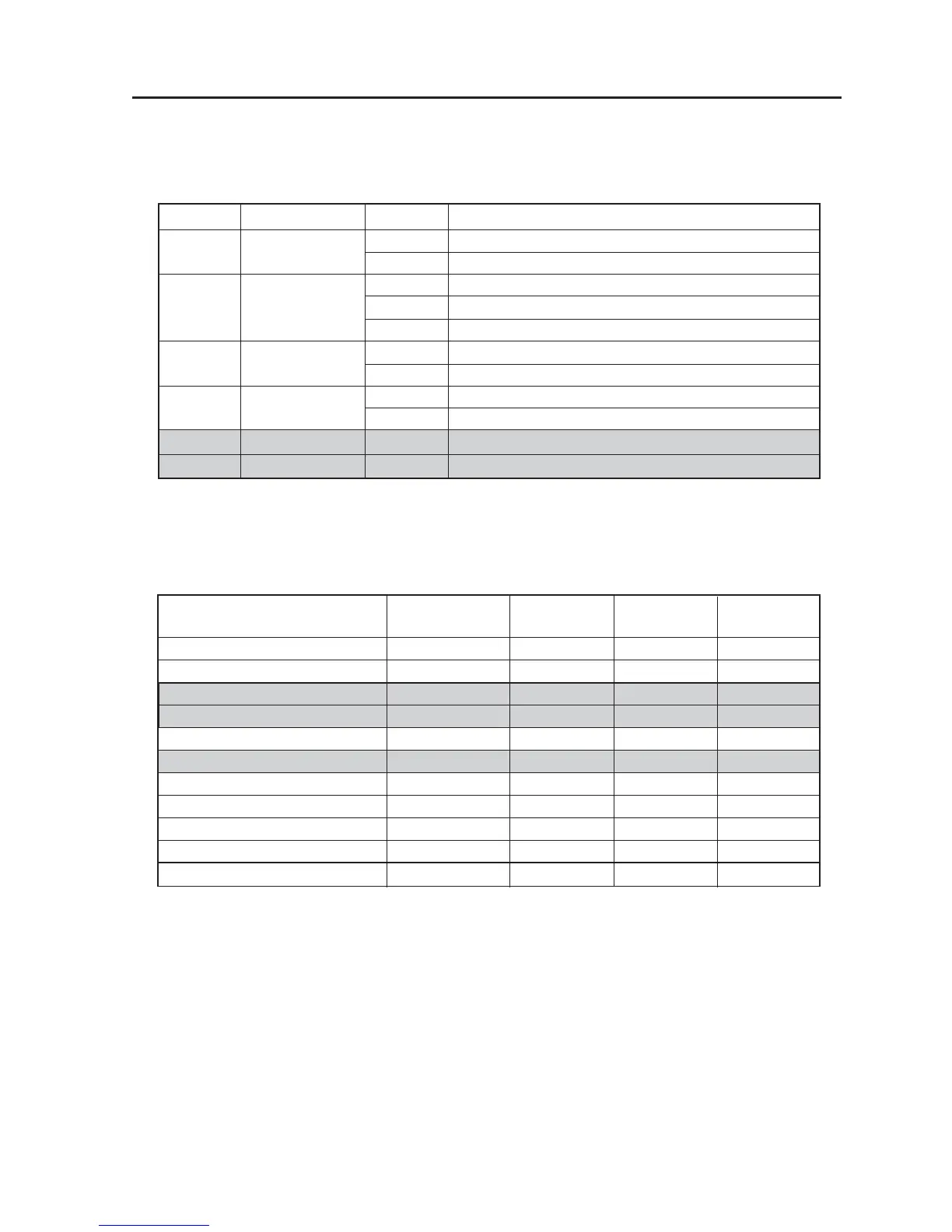
Reference LED Name Color Definition
Green Completion of all configurations (including FSB)
Red Incompletion of configurations
Green PowerGood “High” in steady state
D1 PowerGood Yellow PowerGood “Low”
Red Power and PowerGood events in false state
Green Completion of U15 Sub FPGA configurations
Unlit Incompletion of U15 Sub FPGA configurations
Green Completion of U22 Main FPGA configurations
Unlit Incompletion of U22 Main FPGA configurations
D3 General Purpose — Not use
D4 General Purpose — Not use
Data (Contents) Start Location Size (Bytes) #of Sectors Mbits
(Bytes)
TI Application Software ? Boot 0x00000000 128K 2 1.000
TI Application Software ? Main 0x00020000 512K 8 4.000
OEM Gamma Tables 0x000A0000 64K 1 .500
OEM Data 0x000B0000 64K 1 .500
DMD Data 0x000C0000 64K 1 .500
Spare 0x000D0000 192K 3 1.500
Main FPGA Firmware ? Boot 0x00100000 1024K 16 8.000
Main FPGA Firmware ? Main 0x00200000 1024K 16 8.000
Satellite FPGA Firmware 0x00300000 1600K 25 12.500
Sequence Data 0x00490000 3250K 25 27.500
Total 0x00800000 8192K 128 64.00
5. Status LED
This board is provided with the LEDs specified below intended for the presentation of status information
about the system.
At the time of normal starting, all LEDs are lit in green.
6. Flash memory map
In the U16, the following files with the respective functions are mapped as shown below.
These FW items are furnished by Texas Instruments, Inc.
D5 Reset FPGA