9-47
“Confidential, Do Not Duplicate without written authorization from NEC.”
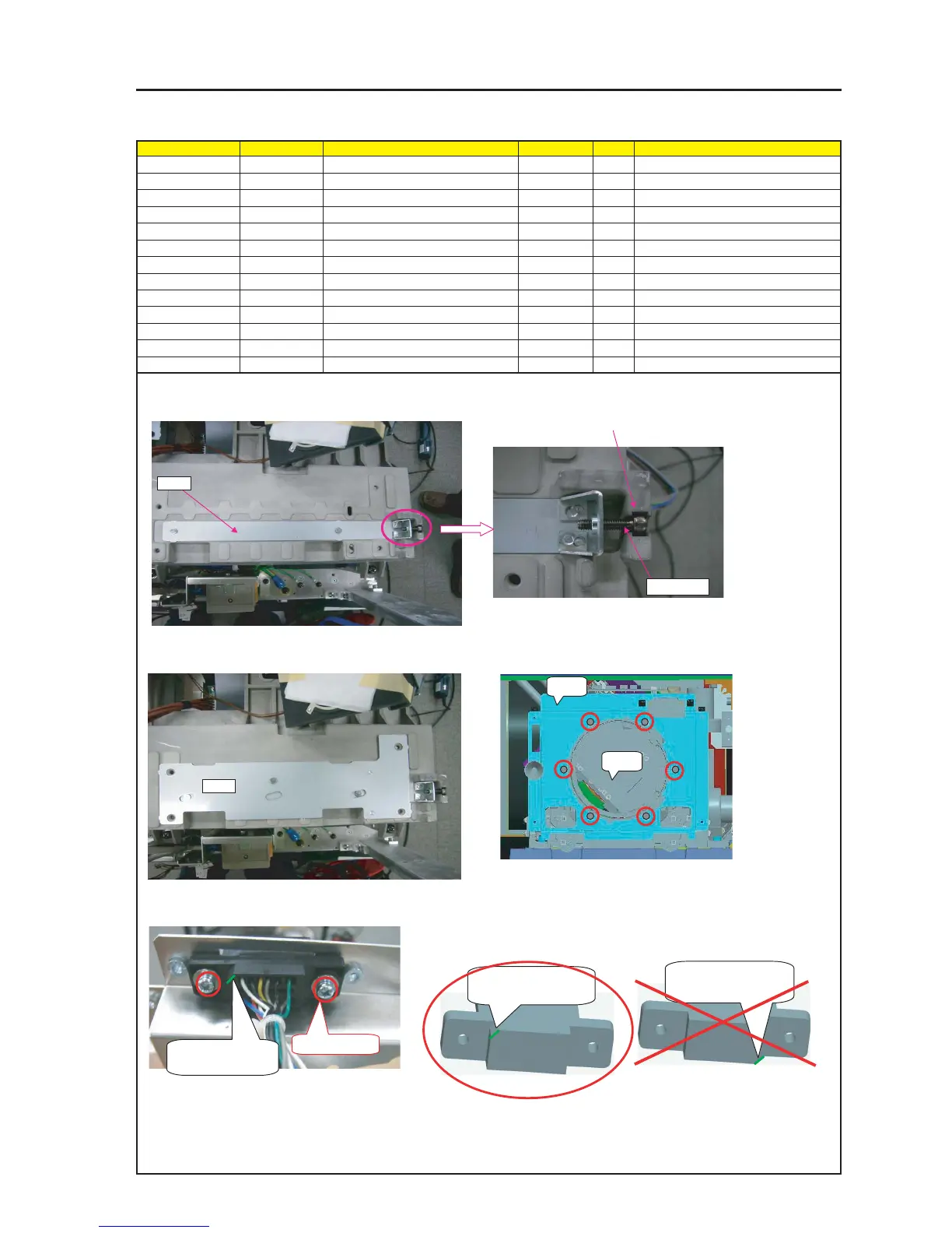
ASSEMBLY DIAGRAM
CAUTION : The installation of the Connector block of the Lens Mount (PA67) shall
conform to the mounting posture as shown at left in the diagram below.
PRT1
1 Mount adjustment screw on Bracket Z-Axis Adjust, put it over
the BASE ENGINE.
3 Put Bracket Translate over Bracket Z-Axis Adjust.
5 Install the connector block of the lens mount (PA67) on the Shield Plate (NC1600C) A.
4 Mount SHIELD PLATE(NC1600C)A on LENS MOUNT(PA67).
Remove LENS HOLDER after mounting.
2 When mounting the adjusting screws (SRW007) on the Bracket Z-Axis
Adjust block, adjust the amount of screw tightening so that their heads
enter the hollow part of the base engine.
PRT2
SRW007
PRT3
PRT4
SRW132 X2P
Where there is a notch
in this section
Where there is a notch
in this section
No notch shall be
allocated in this section.
LENS MOUNT
Diagram symbol Circuit symbol Part name Part code Q’ty Remarks
PRT1 Bracket Z-Axis Adjust 1
Appended Goods of LENS MOUNT(PA67)
SRW007 HHCS*4*16*3KF 24V00451 1
PRT2 Bracket Translate 1
Appended Goods of LENS MOUNT(PA67)
PRT3 SHIELD PLATE(NC1600C)A 24H60931 1
PRT4 LENS MOUNT(PA67) 24BS7791 1
SRW065 CFIMS*3*6*3KF 24V00421 6 Torque check
SRW132 SCREW,PL-CPIMS*3*12*3KF 24V00121 2 Torque check