9-46
“Confidential, Do Not Duplicate without written authorization from NEC.”
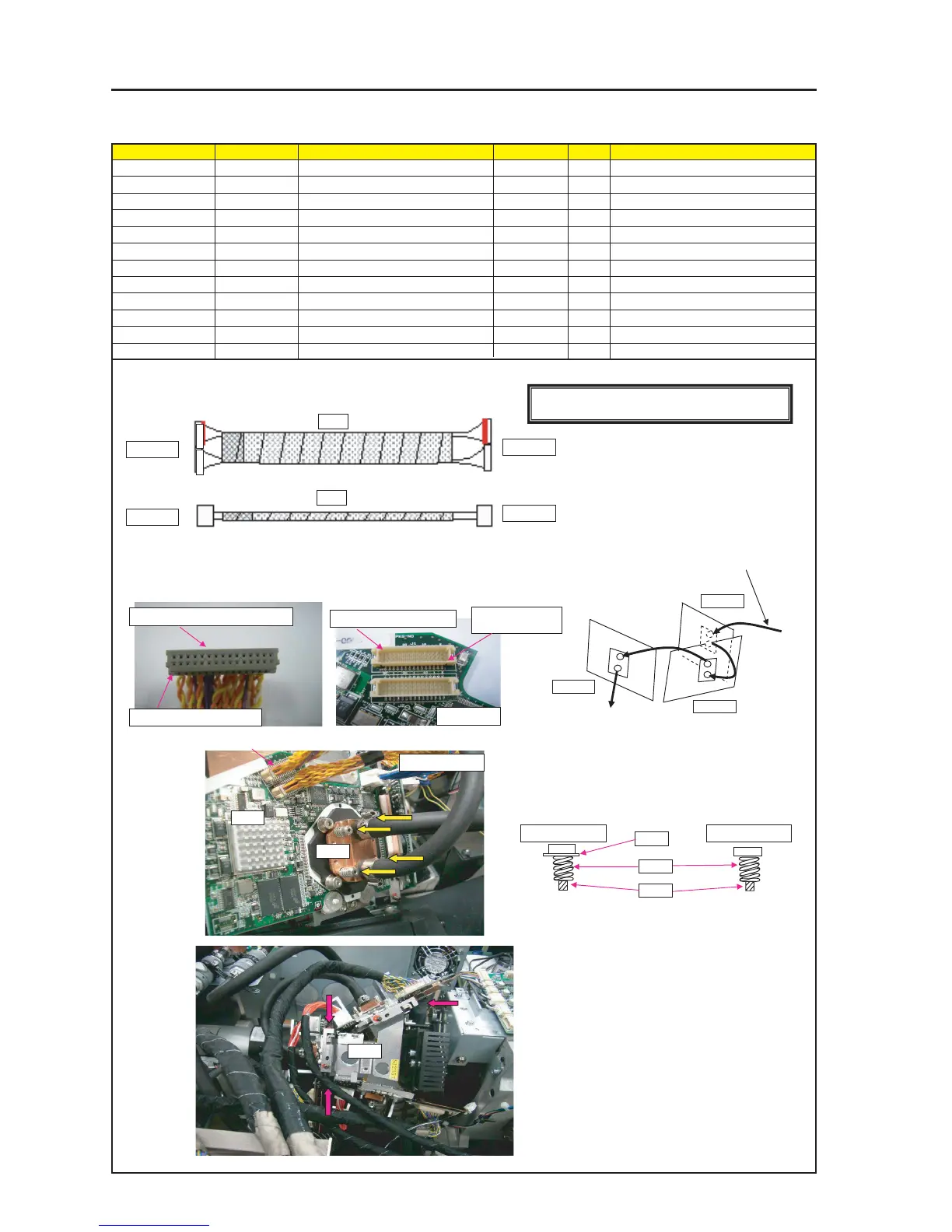
ASSEMBLY DIAGRAM
Diagram symbol Circuit symbol Part name Part code Q’ty Remarks
PRT1 PRISM ASSY 82N94121 1
PRT2 WATER COOLED UNIT(PA67) 24BS7781 1
PRT3 SPRING(K=0.92, L=8.2) 24H45922 12
PRT4 SPECIAL SCREW(M3, D=4) 24N06341 12 Torque check
PRT5 WASHER(D6, T1.5) 24H52701 4
SILICON OIL CONPOUND G747 9E020001
GLUE, SCREW LOCK 92201082
PRISM SASSY
3 Coat evenly with SILICON OIL CONPOUND
G747(200G) on contacting surface of DMD of
WATER COOLED UNIT.
SRW139 X4P
FSB-R
FSB-G
FSB-B
* Insert the red marking side on upside. (All R/G/B PWB)
1 Mounting Instruction for WATER COOLED
UNIT(PA67)
For R For G/B
PR2
PR1
4 Combinational method for Screws and Spring and
Washer when mounting WATER COOLED UNIT.
PR4
PR3
PR5
5 Mount it on OPT ENGINE UNIT using the screws from
PRISM ASSY.
Tightening torque : 13±kgf•cm
GLUE,SCREW LOCK (3parts)
FFIB side
FFIB side
FMT side
FSB PWB
* Carefully check the unevenness of the
housing before insertion.
Hollow side faced upwards
Hollow side faced upwards
Embossed side faced downwards
Embossed side
faced downwards
J7
FSB side
PR1
2 When inserting and pulling the CONNECTOR
J1/J7, put your hand on the BOARD to support it.
[CAUTION] countermeasure against static electricity
Use WRISTSTRAP when handling the Board.
* From pump side to joint
(where adhesion of the LABEL
is provided)
J1