9-45
“Confidential, Do Not Duplicate without written authorization from NEC.”
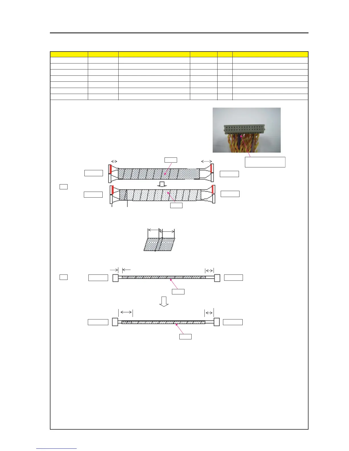
ASSEMBLY DIAGRAM
CABLE
Diagram symbol Circuit symbol Part name Part code Q’ty Remarks
J7 CN30P(J7)360W,1061-28 7NWLW048 6
J1 CN8P(J1)360W,1007-22 7MW8W033 3
PRT1 CONDUCTIVE CLOTH TAPE 9R030011
PRT2 ACETATE CLOTH TAPE 9R030010
J7
PR2
1
The both side of a CONNECTOR "J7" should be marked with red.
* Not to color on TERMINAL (PIN).
Wind a conductive cloth tape together with two connectors "J7."
Then, wind an acetate cloth tape over it.
* The Marker (crimson) to be used shall be an item applicable to
RoHS or equivalent.
FFIB side
FSB side
FFIB side
FSB side
PRT1
40
±
5mm
80
±
5mm
30
±
5mm
J1
* A red marking on the
hollow side
40
±
5mm
40
±
5mm
10
±
5mm
50
±
5mm
Tape
Tape
FFIB side
FFIB side
FSB side
FSB side
2
The amount of tape winding applied to Cables (J1/J7)
shall be 1/3 or more of the tape width.
PRT1
PR2