9-3
“Confidential, Do Not Duplicate without written authorization from NEC.”
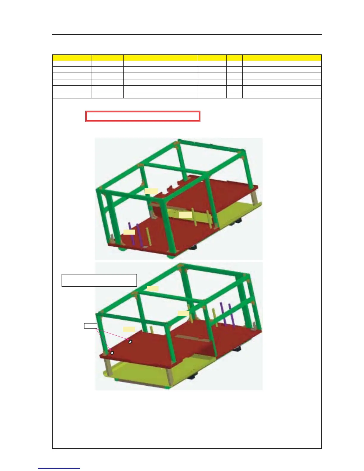
ASSEMBLY DIAGRAM
Diagram symbol Circuit symbol Part name Part code Q’ty Remarks
PRT1 FRAME ASSY 24HS4261 1
PRT2 GROMMET(G-50) 24C07691 2
FRAME1
CAUTION : EMI (Electro Magnetic Interface countermeasure)
1 Positions of gaskets to be stuck to the Frame Assy shall be described following the order of planes (A to F) on the Frame Assy.
In this case, these positions shall be defined as specified below.
Front side
Rear side
* Set GROMMET into the FRAME ASSY
screw hole.
C side
A side
F side
D side
PRT2
E side
B side