9-4
“Confidential, Do Not Duplicate without written authorization from NEC.”
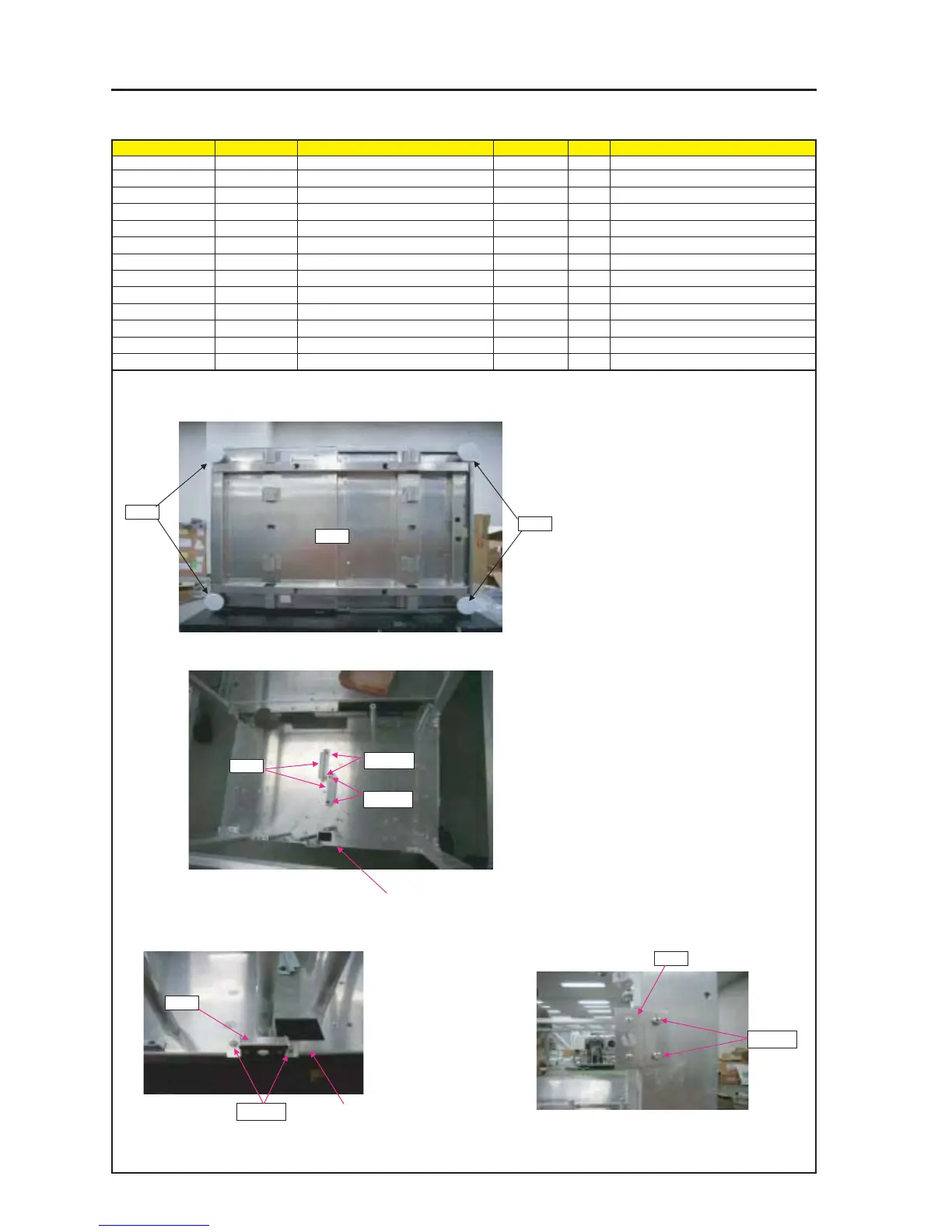
ASSEMBLY DIAGRAM
FRAME
Diagram symbol Circuit symbol Part name Part code Q’ty Remarks
PRT1 FRAME ASSY 24HS4261 1
PRT2 FOOT(RP-70M14) 24C08881 4
PRT3 HOLDING BRACKET 24H55831 2
SRW020 PL-CPIMS*4*10*3KF 24V00461 4 Torque check
PRT4 BRACKET(FB) ASSY 24HS3991 1
SRW071 SCREW,PL-CPIMS*3*8*3GF 24V00111 2 Torque check
PRT5 BRACKET(FA) ASSY 24HS3981 1
SRW070 SCREW,PL-CPIMS*3*8*3GF 24V00111 2 Torque check
PRT1
PRT2
PRT2
2 Place the FOOT(4 pieces) on the rear of the
FLAME.
3 Turn back the FLAME Assy, and set the bracket(2 pieces)
to it.
4 Set the brackets(FB) on the FLAME Assy. 5 Set the brackets(FA) on the FLAME Assy.
Tighten up the screws without any interspace.
Torque : 100±5kgf•cm
1 Check the FLAME Assy screws tightened up.
PRT3
SRW020
SRW020
PRT4
SRW071
* The front side of the FLAME Assy
* The front side of the FLAME Assy
PRT5
SRW070