9-5
“Confidential, Do Not Duplicate without written authorization from NEC.”
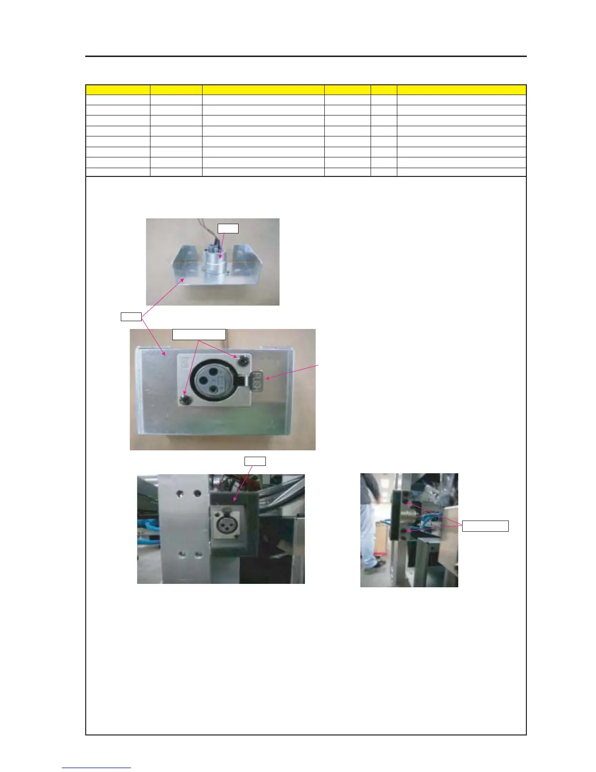
ASSEMBLY DIAGRAM
Diagram symbol Circuit symbol Part name Part code Q’ty Remarks
PRT1 FIXING PLATE(CC) 24H56111 1
ANA CN4-3P(ANA)300W,1061-24 7NW4W047 1
SRW131 SL-CPIMS*2.5*8 24V00181 2 Torque check
PRT2 SHIELD PLATE(CC) 24J29021 1
SRW022 PL-CPIMS*4*10*3KF 24V00461 2 Torque check
ANA
PRT1
PRT2
1 Mount Connector "ANA" on the stationary plate (CC).
2 When the FIXING PLATE set on the FLAME, the PUSH
side of the "ANA" should be upward.
3 Set the CC on the FLAME, and set the SHIELD PLATE(CC) on
the FIXING PLATE.
SRW131 x2p
SRW022 x2p
ANA