9-6
“Confidential, Do Not Duplicate without written authorization from NEC.”
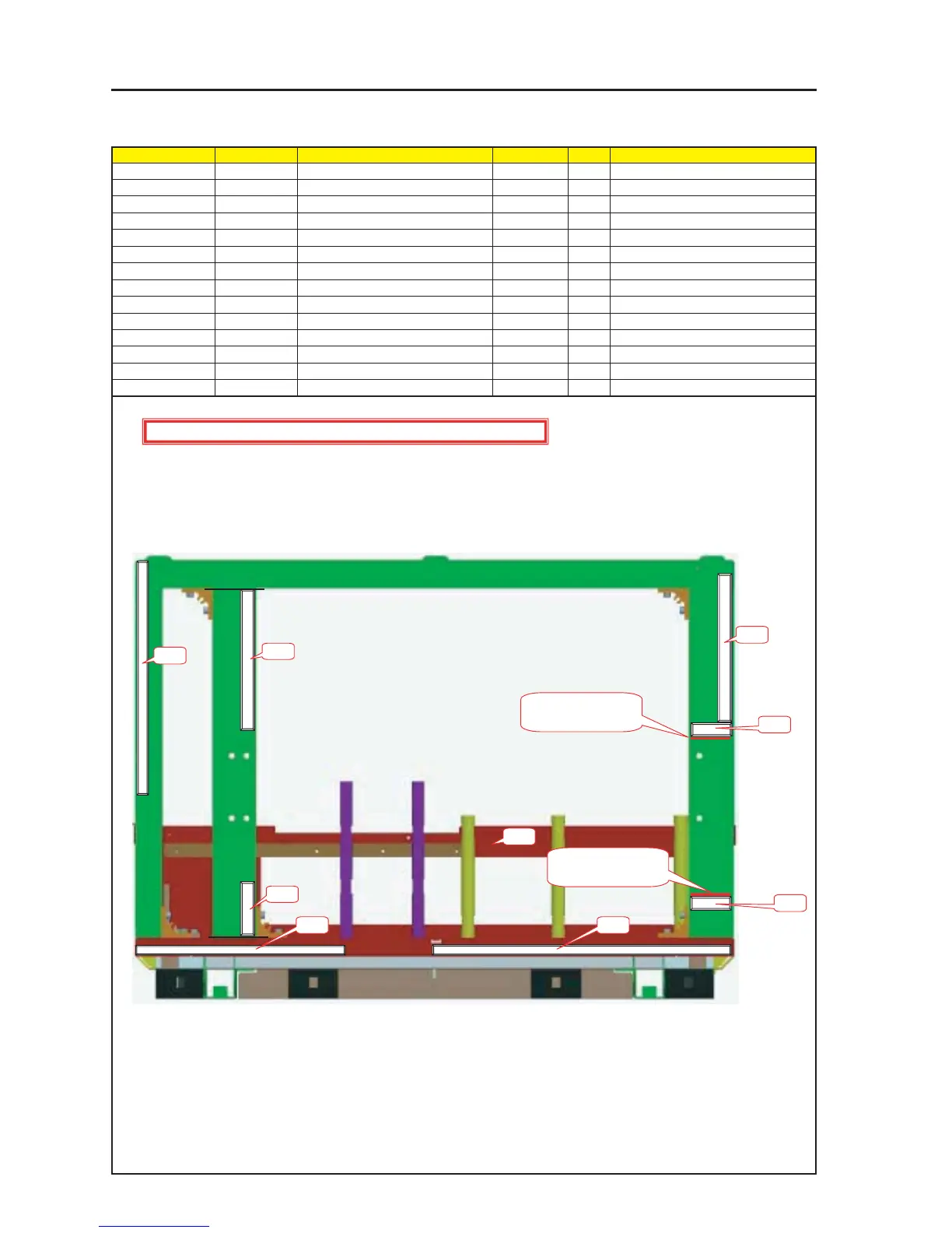
ASSEMBLY DIAGRAM
Diagram symbol Circuit symbol Part name Part code Q’ty Remarks
PRT1 FRAME ASSY 24HS4261 1
PRT2 GASKET(STG15-10) 24C06081 1 160mm
PRT3 GASKET(STG15-10) 24C06081 1 30mm
PRT4 GASKET(STG10-10) 24C05351 1 340mm
PRT5 GASKET(STG7-10) 24C08591 1 170mm
PRT6 GASKET(STG7-10) 24C08591 2 50mm
PRT7 GASKET(STG7-10) 24C08591 1 380mm
PRT8 GASKET(STG0.5-8) 24C07561 1 280mm
FRAME1_A
1 GASKET(STG15-10) should be 30mm and 160mm each, and paste it on the FRAME ASSY.
2 GASKET(STG10-10) should be 340mm long, and paste it on the FRAME ASSY.
3 GASKET(STG7-10) should be 50mm/170mm and 380mm each, and pasteit on the FRAME ASSY.
4 GASKET(STG0.5-8) should be 280mm and 680mm each, and paste it on the FRAME ASSY.
PRT2 should be pasted based on inside of the Terminal area.
PRT3 should be pasted based on inside of the Terminal area.
PRT4 should be pasted based on upper left to outside.
PRT5 should be pasted begin at PRT6 based on outside.
PRT6 should be pasted based on outside(upside or lower side) of the insection.
PRT7 should be pasted based on lower left.
PRT8 should be pasted based on lower right.
PRT2
PRT3
PRT6
PRT6
PRT1
CAUTION : EMI (Electro Magnetic Interference : radio disturbance) countermeasure
The PRT6 should be
pasted on the upperside
of the insection.
The PRT6 should be
pasted on the undersied
of the insection.
PRT4
PRT5
PRT7PRT8