9-32
“Confidential, Do Not Duplicate without written authorization from NEC.”
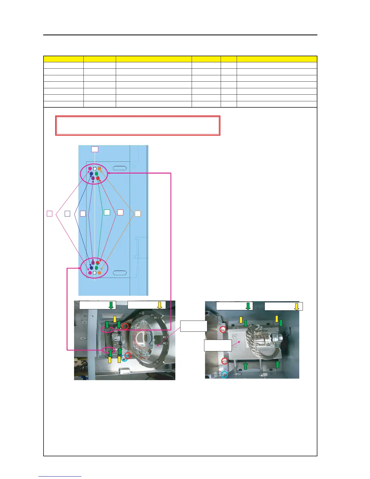
ASSEMBLY DIAGRAM
Diagram symbol Circuit symbol Part name Part code Q’ty Remarks
PRT1 REFLECTOR BASE(PA67) 12JT1801 1
SRW001 PL-CPIMS*4*16*3GF 24V00471 8 Torque check
LAMP2 (3)
1 Put the reflector base on the lamp base and fix it.
For fixing, the Lamp Base Assy pin shall be applied to the
Reflector Base (PA67).
When putting the reflector base on the lamp base, use a
protection mask and wear protection gloves.
2 When fixing the reflector base to the lamp base, fix the screws
in the positions of –2, –4, –6 or +2, +4, +6 according to the numerical
values of measuring positions listed in the Inspection Qualification Table.
The Inspection Qualification Table shall be stuck to the History Table.
-6 -4 -2
+2 +4
+6
SRW078 X2P
SRW001 X4P
PRT1
positive post
±0
PRT1
negative post
SRW078 X3PSRW001 X4P
Beyond this point, Lamp operation should be in the LAMP ROOM for ensuring safety
* Apply the reflector base (PA67) to the lamp fan side and fix it with the screws indicated by the green arrow mark.
Then, remove the screws encircled in red and tighten the screws encircled in blue.
The tightening torque for the screws encircled in blue shall be 12 ~ 14kgf•cm.