9-33
“Confidential, Do Not Duplicate without written authorization from NEC.”
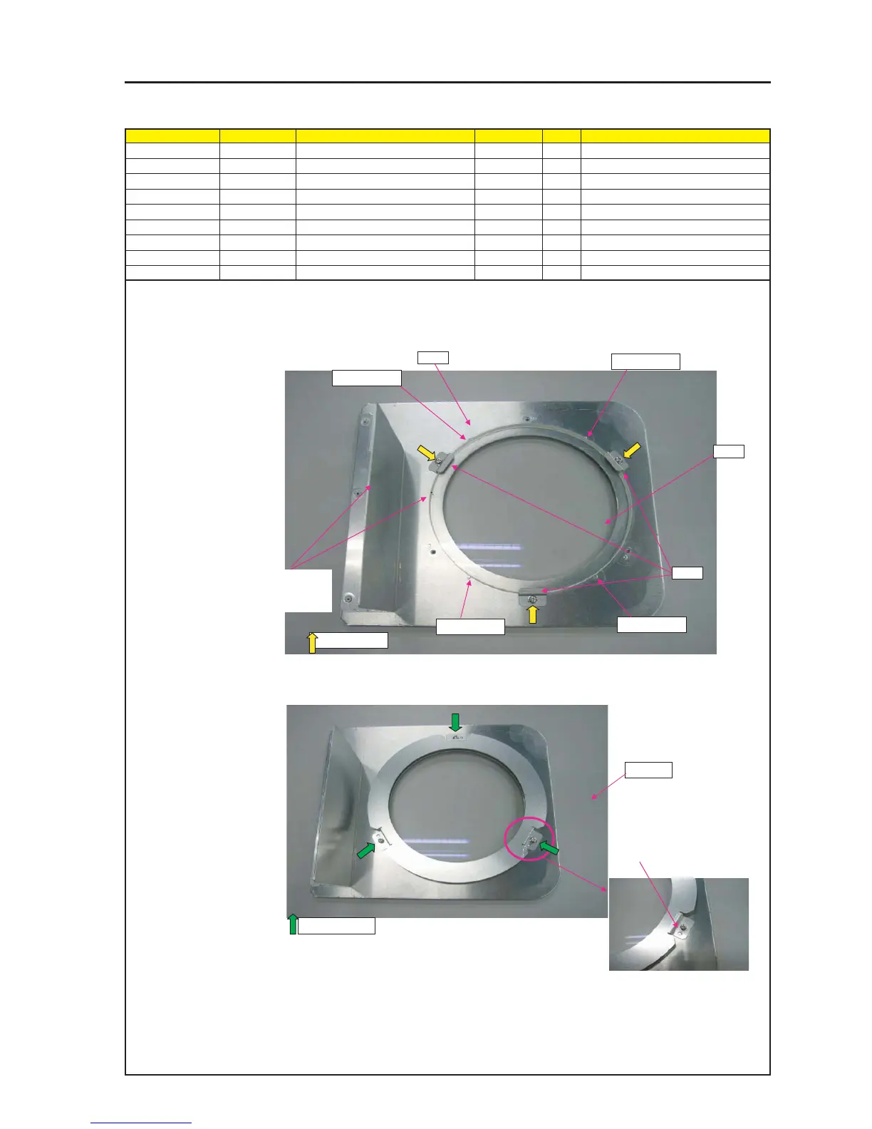
ASSEMBLY DIAGRAM
UV GLASS
Diagram symbol Circuit symbol Part name Part code Q’ty Remarks
PRT1 UV GLASS(PA67) 12JT1791 1
PRT2 BASE(GLASS)ASSY 24HS4351 1
PRT3 HOLDING PLATE(UV GLASS) 24H60271 3
SRW048 SCREW,PL-CPIMS*3*8*3GF 24V00111 3 Torque check
PRT4 COVER(GLASS) 24H60171 1
SRW046 SCREW,PL-CPIMS*3*8*3GF 24V00111 3 Torque check
PRT1
PRT2
1 Put the UV glass fitted to the round bosses (4 pcs.) of the base (Glass) Assy and fix it with
a holding plate (UV Glass). (Where round bosses are not allocated)
SRW048 X3P
PRT4
4 Fit it to the round bosses.
SRW046 X3P
PRT3
2 Mount the UV GLASS so that its marking
side is faced to the PLATE side.
(Outside direction)
3 Attach COVER(GLASS) over BASE(GLASS)ASSY.
Round bosses
Round bosses
Round bosses
Round bosses