9-34
“Confidential, Do Not Duplicate without written authorization from NEC.”
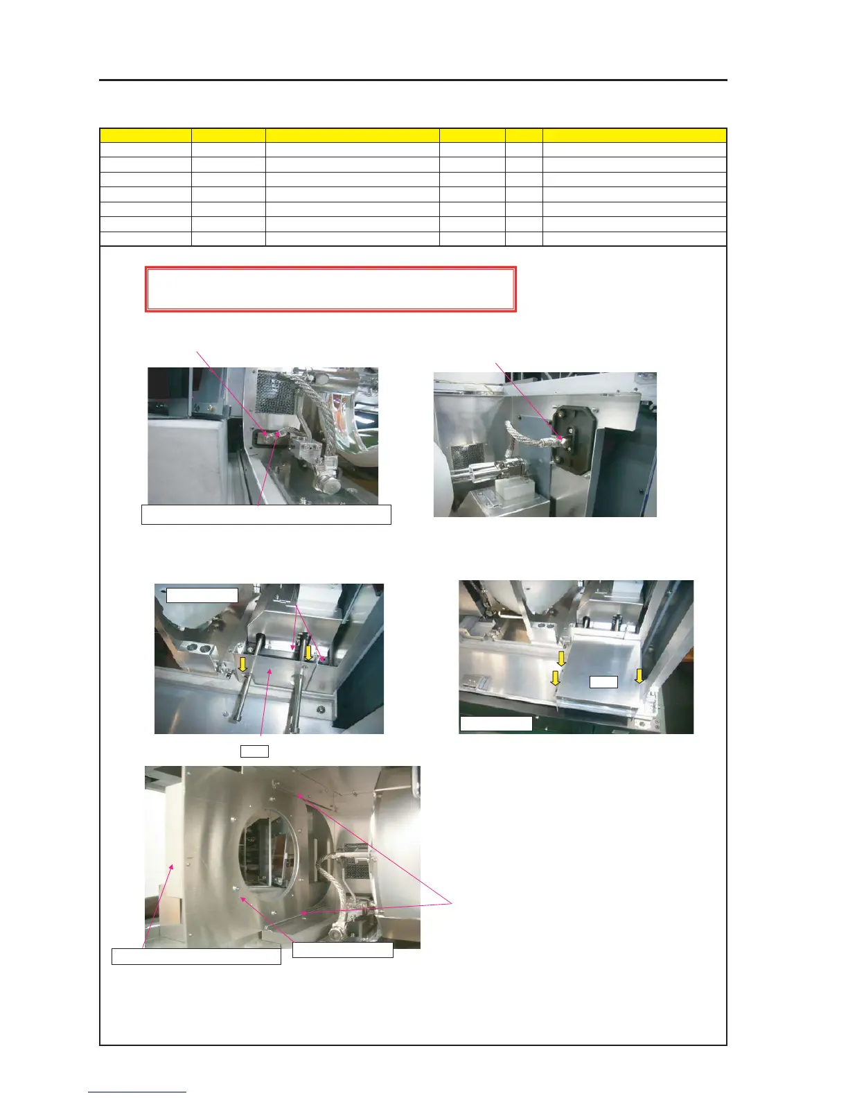
ASSEMBLY DIAGRAM
Diagram symbol Circuit symbol Part name Part code Q’ty Remarks
PRT1 DUCT(LAMP) 24H60251 1
SRW047 PL-CPIMS*4*10*3KF 24V00461 3 Torque check
PRT2 LAMP COVER S(BOTTOM) 24H61261 1
SRW078 PL-CPIMS*4*10*3KF 24V00461 2 Torque check
LAMP3
PRT1
1 Remove the screws of Positive Post Terminal Plate, and attach
it using unscrewed screws from Reflector base Positive Post
Cable.
3 Remove the wire harness band that is attached to the optical axis
adjusting bar.
(Cut it off)
Attach LAMP COVER S (BOTTOM) on LAMP BASEASSY.
4 Get the optical axis adjusting bar of the reflector base passed
through the guide hole of the duct lamp and mount the assembly
on the frame Assy.
SRW047 X3P
5 Fit BASE(GLASS) SASSY into LAMP COVER S ASSY
GUIDE RAIL.
BASE (GLASS) SASSY
2 Remove the screws of Negative Post Terminal Plate, and attach
it using unscrewed screws from Reflector base Negative Post
Cable.
PRT2
SRW078 X2P
Beyond this point, Lamp operation should be in the LAMP ROOM for ensuring safety