9-43
“Confidential, Do Not Duplicate without written authorization from NEC.”
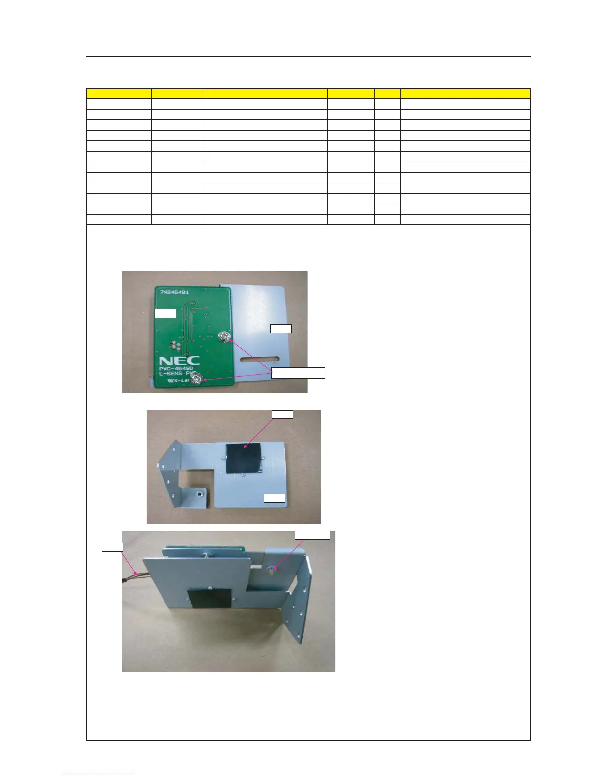
ASSEMBLY DIAGRAM
L-sens
Diagram symbol Circuit symbol Part name Part code Q’ty Remarks
PRT1 L-SENS PWB ASSY 81N94ZG1 1
SRW140 PL-CPIMS*3*8*3GF 24V00111 2 Torque check
PRT2 FILTER(SENSOR) 24J28671 1
PY CN4P(PY)800W,1061-28 7NW4W053 1
PRT3 HOLDER(SENSOR) 24H59981 1
PRT4 BRACKET(SENSOR) 24H59971 1
SRW032 PL-CPIMS*3*6*3KF 24V00571 1 Torque check
PRT1
PRT4
1 Attach CIRCUIT PROTECTOR (6N500018) on BRACKET (TAMPER) A.
2 Peel off a protection sheet from the adhesive tape of the
filter (sensor) and stick the filter to the holder (sensor) by
applying it to the three round bosses on the holder.
3 Assemble the respectively assembled holders (sensor)
and mounting metal fittings (sensor).
* The PY connector shall be assembled after it has
been inserted in advance.
* Remove the FILTER(SENSOR) film.
SRW032
SRW140 X2P
PRT3
PRT2
PY