9-42
“Confidential, Do Not Duplicate without written authorization from NEC.”
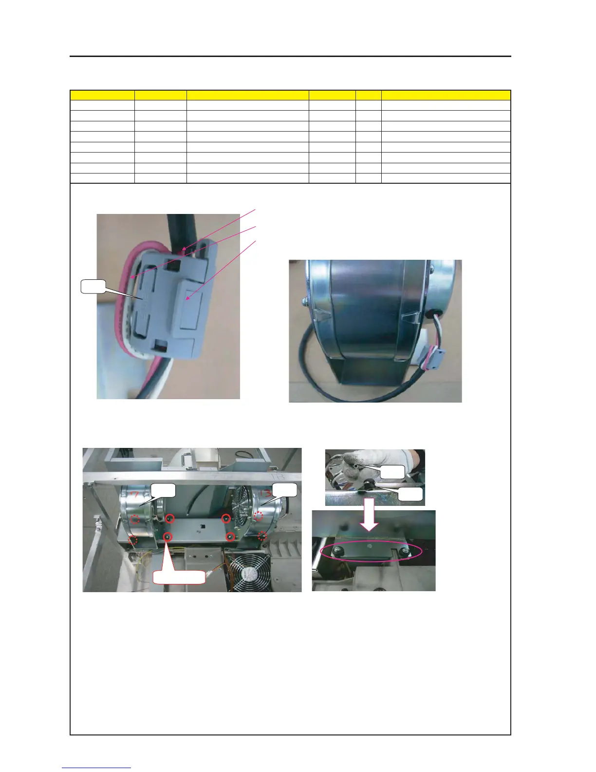
ASSEMBLY DIAGRAM
Diagram symbol Circuit symbol Part name Part code Q’ty Remarks
PRT1 DCFAN BL6771 3N170122 2
PRT2 CUSHION 24C09141 8
PRT3 COLLAR 24C09171 8
PRT4 SRW111 PL-CPIMS*3*15 24V00251 8 Torque check
PRT4 CORE E04SR200932 6N160014 2
MOUNT L-FAN
1 Attach CORE on DC Fan BL6771.
2 Set Fan after attaching Cushion and Collar on DC Fan BL6771.
3 Fit a cushion material to the DC fan base. Put the DC fan on the
mount (L-fan) and fix it through a collar.
* Mount it until it stops at the root of the black tube.
* Pass the fan cable twice through the ferrite core and wind it once.
* When closing the core, make sure not to pinch the cable.
Fasten the hook.
* Fit a cushion material to
the DC fan and fasten it
with screws after a collar
has been passed.
PRT4
PRT1
PRT1
PRT2
PRT3
SRW111 X 8P