9-41
“Confidential, Do Not Duplicate without written authorization from NEC.”
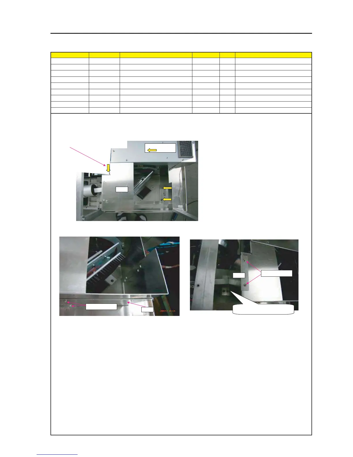
ASSEMBLY DIAGRAM
1 Attach SHIELD PLATE (ENGINE) B on LAMP BASE ASSY.
2 Attach SHIELD PLATE (ENGINE) D on SHIELD PLATE (ENGINE) B. 3 Attach SHIELD PLATE (ENGINE) E on SHIELD PLATE (ENGINE) B.
This screw shall be tightened together
with the Shield Plate (Lamp Cable).
SRW041 X3P
PRT1
SRW043 X2P
PRT1
SRW059 X2P
PRT3
The lower-side hook shall be fitted
assuredly.
ENGINE 2
Diagram symbol Circuit symbol Part name Part code Q’ty Remarks
PRT1 SHIELD PLATE(ENGINE)B 24H60101 1
SRW041 PL-CPIMS*4*10*3KF 24V00461 3 Torque check
PRT2 SHIELD PLATE(ENGINE)D 24H60121 1
SRW043 SCREW,PL-CPIMS*3*8*3GF 24V00111 2 Torque check
PRT3 SHIELD PLATE(ENGINE)E 24H60861 1
SRW059 SCREW,PL-CPIMS*3*8*3GF 24V00111 2 Torque check