9-40
“Confidential, Do Not Duplicate without written authorization from NEC.”
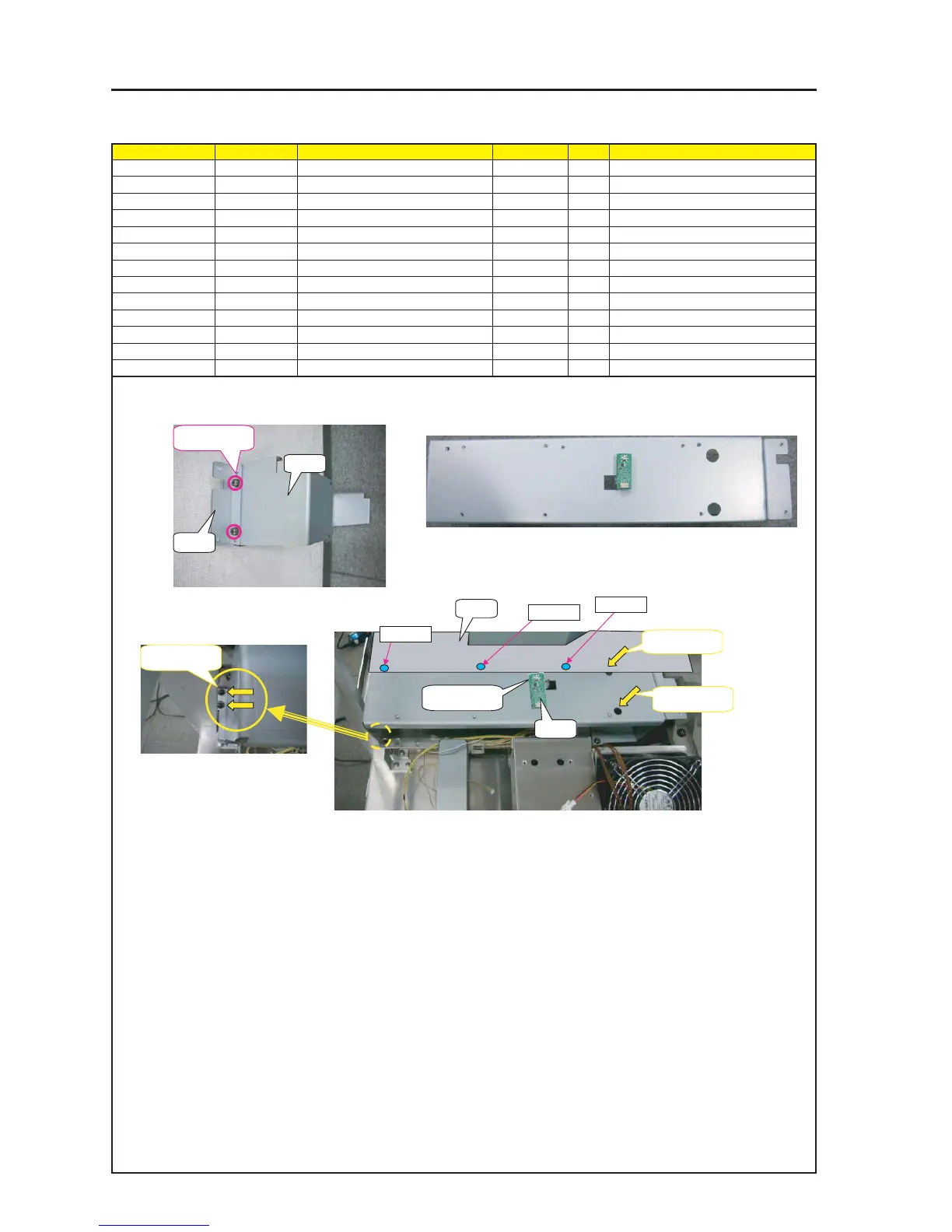
ASSEMBLY DIAGRAM
Diagram symbol Circuit symbol Part name Part code Q’ty Remarks
PRT1 MOUNT(L-FAN) 24H60831 1
PRT2 MOUNT(L-FAN)S 24H60841 1
SRW057 PL-CPIMS*5*12*3KF 24V00151 2 Torque check
SRW056 PL-CPIMS*4*10*3KF 24V00461 4 Torque check
PWB1 LSES PWB ASSY 1
SRW127 SCREW, PL-CPIMS*3*8*3GF 24V00111 1 Torque check
PRT3 SHIELD PLATE(LAMP CABLE) 24H61331 1
SRW073 SCREW,PL-CPIMS*3*8*3GF 24V00111 3 Torque check
MOUNT L-FAN
3 After putting MOUNT (L-FAN) over the FLAME and fix
it, attach Shield Plate(Lamp Cable) over it.
1 Attach MOUNT (L-FAN) and MOUNT(L-FAN)S
PRT1
PRT2
SRW057 x 2P
SRW056 X2P
SRW056 X2P
SRW05 X2P
SRW***
SRW***
SRW***
2 Attach L SENS PWB ASSY on MOUNT(L-FAN).
SRW127 X1P
PRT3
PWB1