9-39
“Confidential, Do Not Duplicate without written authorization from NEC.”
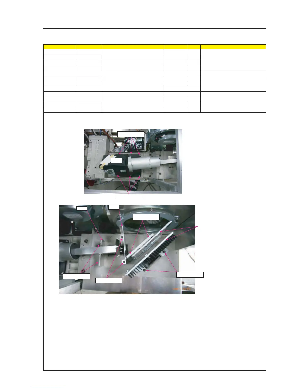
ASSEMBLY DIAGRAM
ENGINE 1
Diagram symbol Circuit symbol Part name Part code Q’ty Remarks
PRT1 OPT ENGINE(PA67) 24BS7771 1
SRW002 HHCS*5*16*3GF 24V00501 6 Torque check
PRT2 SHIELD PLATE(ROD) 24H60131 1
SRW045 PL-CPIMS*4*10*3KF 24V00461 2 Torque check
PRT3 SHIELD PLATE(ENGINE)C 24H60111 1
SRW042 PL-CPIMS*4*10*3KF 24V00461 2 Torque check
SRW028 PL-CPIMS*4*10*3KF 24V00461 2 Torque check
SRW030 PL-CPIMS*4*10*3KF 24V00461 2 Torque check
PRT1
PRT2
1 Attach OPT ENGINE(PA67) over ENGINE BASE.
2 Attach SHIELD PLATE(ENGINE)C before attaching ENGINE.
Be careful for attachment direction of SHIELD PLATE(ROD).
SRW002 X3P
SRW002 X3P
3 Attach HEAT SINK ASSY.
Attach COLD MIRROR ASSY.
SRW030 X2P
SRW042 X2P
SRW045 X2P
PRT3
SRW028 X2P