CONNECTION DIAGRAMS
“Confidential, Do Not Duplicate without written authorization from NEC.”
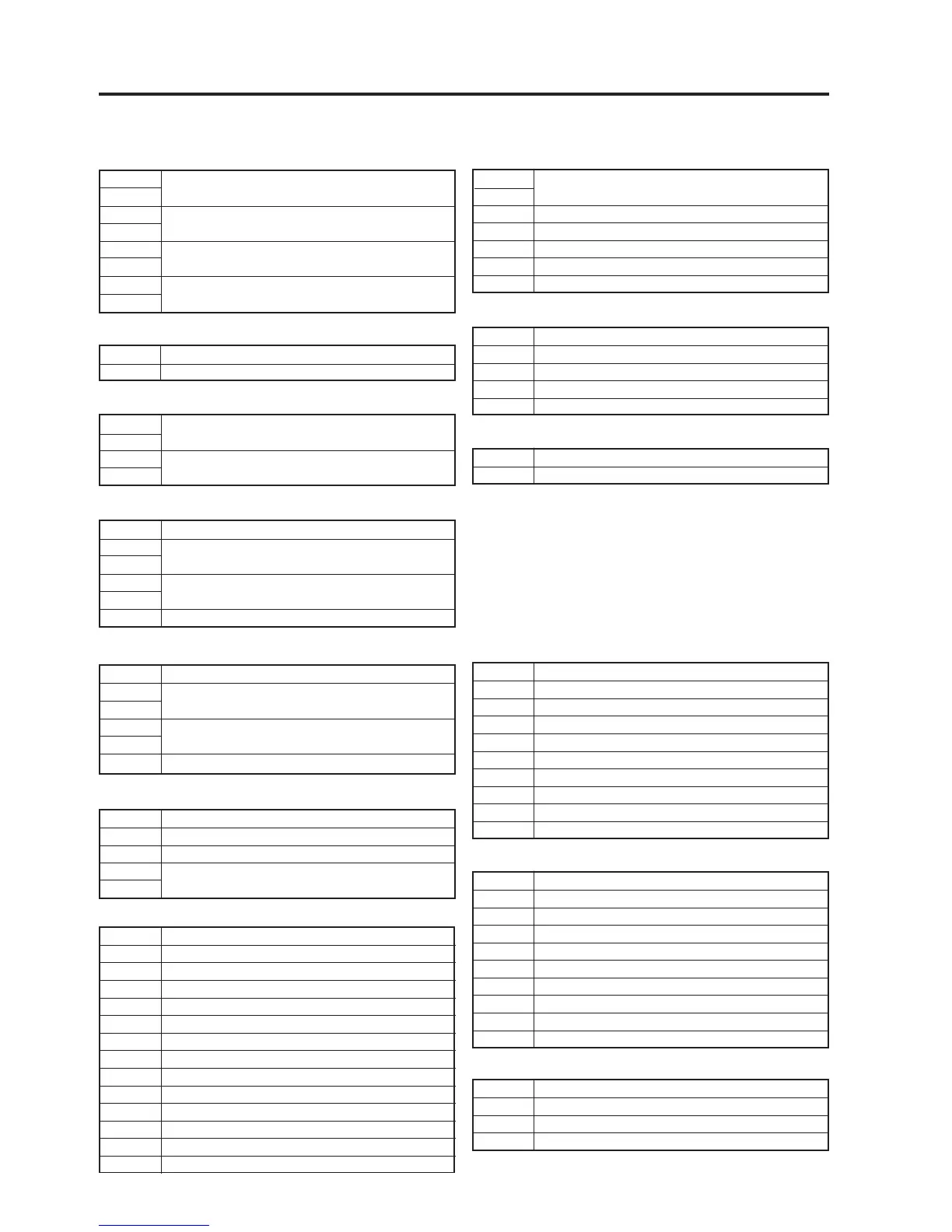
POCP Connect to CPU PWB
1
2
3 GND
4NC
5 GND
6 5V Main
7 GND
PODO Connect to DVI-OUT PWB
1 5V Main
2 GND
3 3.3V (Regulated)
4 GND
5 Power BIT (L : Power ON H : Power off)
PON10 Connect to MOTHER PWB
1 Power good (L : Power OK H : Power NG)
2 GND
3 12V Main for TI board
4 GND
5 5V Main for TI board
6 GND
7 3.3V Main for TI board
8 GND
9 3.3V Main for TI board
10 GND
12-5
PJDIV PWB (PWC-4691A) 1/4
POPSS1 Connect to Standby PS
1
2
3
4
5
6
7
8
POPSS2 Connect to Tach panel (Option)
1 24V Standby
2 GND
POPSM4 Connect to Main PS
1 GND
2 FAN Stop in Main PS (L : Normal H : Fan Stop)
3 3.3V module fail of Main PS (L : Normal H : Fail)
4 GND
5 Feedback line of 3.3V voltage
6 5V module fail of Main PS (L : Normal H : Fail)
7 GND
8 Feedback line 5V voltage
9 12V module fail of Main PS (L : Normal H Fail)
10 GND
11 Feedback line of 12V voltage
12 24V module fail of Main PS (L : Normal H : Fail)
13 GND
14 Feedback line of 24V voltage
GND
24V Standby
GND
5V Standby
POPSM1 Connect to Main PS
1
2
3
4
3.3V Main
GND
POPSM2 Connect to Main PS
1 5V main
2
3
4
5
6 GND
GND
5V Main
POPS Connect to MM2000B (Option)
1 5V main
2
3
4
5
6 GND
GND
5V Main
POPSM3 Connect to MOTHER PWB
1 12V main
2 GND
3 24V Main
4
5
GND
5V Standby
POLAN Connect to EHTER PWB
1 5V Standby
2 GND
PON11 Connect to MOTHER PWB
1 Power good (L : Power OK H : Power NG)
2 GND
3 12V Main for TI board
4 GND
5 5V Main for TI board
6 GND
7 3.3V Main for TI board
8 GND
9 3.3V Main for TI board
10 GND
POPF Connect to MOTHER PWB
1 Feedback line of 3.3v voltage
2 GND
3 Feedback line of 5.5V voltage
4 GND