RADIO DEVICES
OPERATION
ALARM: Any Ness radio device can operate
on any zone along with the hardwired zone
input if necessary. Hardwired zones continue
to operate as normal. (This would be the same
as wiring two PIRs in series to one zone).
Radio Keys can also operate on radio zones
for special purposes, but they should normally
be programmed to a user code.
KEYSWITCH INPUT: A Radio Device pro
-
grammed to Zone 8 will still work as an alarm
even if the Zone 8 input operation has been
changed to Keyswitch operation. The P60E
3E option only affects the Zone 8 terminal
inputs.
VIBRATION: Radio device zone signals
IGNORE the P30E–P38E vibration sensor
settings.
TAMPER REPORT: Radio Device Tamper
operation depends on the Armed State of the
control panel.
RADIO TAMPER: causes the keypad to
continuously beep and also to flash the
RADIO, TAMPER and the ZONE (identifying
the detector) lights. Pressing any key on the
keypad or sending a TAMPER RESTORE will
clear this warning.
LOW BATTERY REPORT:
A low battery
gives 10 beeps and flashes the RADIO & the
BATTERY light. The ZONE light identifying the
radio device is also ON. The flashing lights stop
when any key on the keypad is pressed or a
detector code with no low battery is received.
Low Battery generates HISTORY and DIALLER
reports ONCE only (until the low battery is fixed
and a restore report is received).
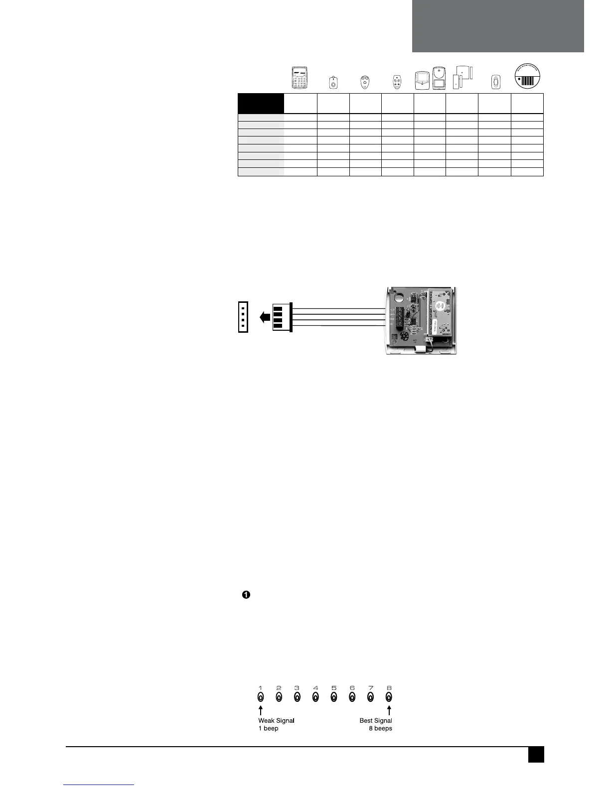
NESS RADIO INTERFACE
The Ness Radio Interface (100–200) is the optional radio receiver required to enable all
radio functions. Connection to the control panel is via a 4 wire loom and plug supplied
with the Ness Radio Interface.
When the Ness Radio Interface is installed, the keypad will flash the RADIO light ON
when any radio signal is detected (from both programmed and non-programmed radio
devices).
+12VRED
J2
RECEIVER
DATA
WHITE
RSSIBLUE
OVBLACK
NESS RADIO INTERFACE
Part No. 100–200
NESS ECO8X
CONTROL PANEL
NOTES
• The Ness Radio Interface is normally installed inside the control panel box.
• In cases where the receiver needs to be located closer to the transmitters, the Ness Radio
Interface can be installed up to 50 metres away from the control panel. Use 14/0.20 shielded
cable or equivalent. The shield can either be connected to the EARTH connection or left
unconnected. Leave the shield unconnected at the receiver end.
• If the Radio Interface must be installed inside a metal enclosure, the antenna wire should
protrude outside the enclosure.
• For best performance, the antenna wire should be kept straight and not coiled, shortened
or extended.
• The optional 100-046 Whip Antenna can be used in cases where radio reception is
marginal. The whip antenna may not improve reception in all cases, however its reception
pattern may better suit the local radio environment.
RK1 RADIO KEY
PENDANT
RKP
RADIO KEYPAD
100-683100-001
RK3 RADIO KEY
3 BUTTON
RK4 RADIO KEY
4 BUTTON
100-664 100-067
R12 RADIO PIR
R15 RADIO PIR
100-691/100-663
RR1/RR2 RADIO
REED SWITCH
RPB RADIO
EMERG BUTTON
100-662/100-527 100-283
RSM RADIO
SMOKE DETECTOR
106-040
SIGNAL
TYPE
NESS RADIO DEVICES
Radio Events Table
ALARM
ARM / DISARM
PANIC button PANIC button PANIC button
yes
yesyes
yes
PANIC button* [star buttons]
yes yes
yes
yes
yes
yes (100-691)
yes yes yes
yes
yes yes yes
ON/OFF buttons ON/OFF buttons15 User IDs
yes yes yes
RESTORAL
LOW BATT
AUX
PANIC
TAMPER
SUPERVISION
O
F
F
O
N
PA
N
IC
RK P
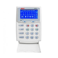
RADIO SIGNAL STRENGTH TEST
The Signal Strength Test can be used to test the radio signal from any Ness radio
device. The strength of the radio signal received is displayed on the zone lights 1–8
and beeped by the keypad.
The higher the number displayed (and beeped) the stronger the signal received.
TEST SEQUENCE:
Enter the option for the radio device to be tested
For Radio Keys: options P11E–P25E. For Radio Devices, options P01E–P08E.
Press 3E
Trigger the radio device
• One of zone lights 1 to 8 will turn ON to indicate the signal strength from the transmitter.
• The Signal Strength display remains on until another command is entered.
• To clear the display and re-test the transmitter, simply press 3E again.
NOTES
• Signal strength of Radio Keys can
be tested in USER PROGRAM Mode or
INSTALLER PROGRAM Mode.
• Signal strength of all other Radio
Devices is tested in INSTALLER
PROGRAM Mode.
• PRESS 3E to test the signal strength
of the selected transmitter ONLY. (Other
devices will be ignored).
• PRESS
4E to test the signal strength of
ANY Ness transmitter (including unpro-
grammed devices).
47
Ness eCO8x CONtrOl PaNel – INstallatION MaNual
NESS RADIO