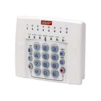
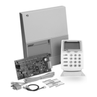
KEYPAD
The Ness ECO8x keypad provides
important visual and audible indication
of the system status and is the main
interface for controlling the many
powerful features of the system.
NUMBER OF KEYPADS
Up to 3 keypads can be connected to
the ECO8x panel.
KEYPAD INSTALLATION
Connect the wires to the screw
terminals as per the wiring diagram
shown in this manual.
The keypad housing can be screwed
directly to the wall through the screw
holes on the front of the fascia. Cover
plugs for the mounting holes are
supplied. Left and right hand cover
plugs are different, (marked 'L' and 'H'
on the inside of the plug).
CABLE LENGTH
The maximum allowable cable length
is 100m (total cable length to all
keypads).
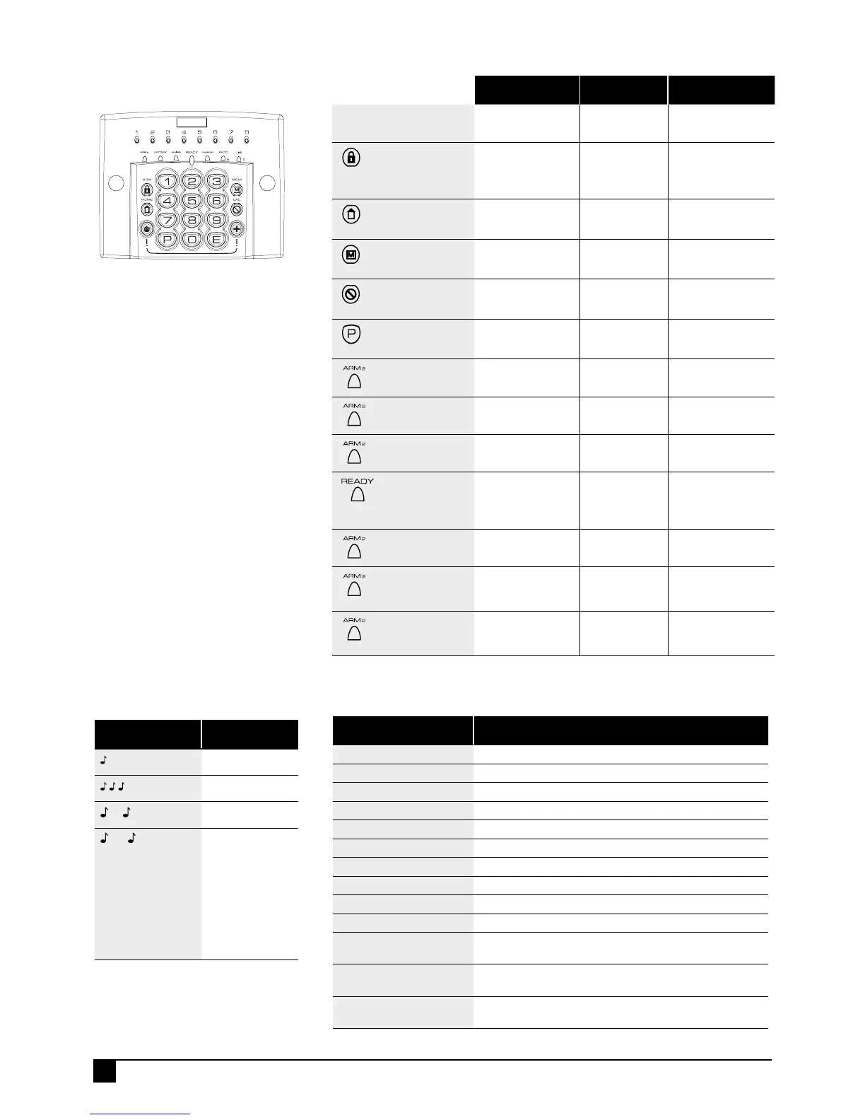
KEYPAD DISPLAY INDICATORS IN MEMORY MODE
KEYPAD LIGHT MEMORY EVENT
Zone lights 1–8 Zone alarm
(no lights) Panel Disarmed
ARMED Panel Armed (or Area 1 Armed)
ARM2
Area 2 Armed
MAINS Mains power failure
BATTERY Low Battery
TAMPER Tamper alarm
EXCLUDE Panic alarm
LINE Telephone line fail
RADIO, EXCLUDE Radio Key Panic alarm
RADIO, BATTERY, ZONE Radio Device battery low, (Device number is indicated by
zone lights)
RADIO, BATTERY, ARM Radio Key battery low, (Radio Key number is NOT
indicated)
RADIO, TAMPER, ZONE Radio Device tamper alarm (Device number is indicated by
zone lights)
KEYPAD DISPLAY INDICATORS IN OPERATING MODE
KEYPAD LIGHT OFF ON FLASHING
ZONE LIGHTS 1-8
Zone is sealed. Zone is
unsealed.
Zone is in alarm.
ARMED
Red Illuminated button
Panel is disarmed. Panel is armed
(or Area 1 is
armed if using
Areas).
HOME
Yellow Illuminated button
Home Mode is
disarmed.
Panel is armed
in Home Mode.
Day Mode enabled,
(see page 18).
MEMORY
Red Illuminated button
Normal. Memory mode
selected.
New alarm/s in
memory.
EXCLUDE
Red Illuminated button
Normal. Zone/s are
Excluded.
PROGRAM
Red Illuminated button
Normal. User Program
Mode.
Installer Program
Mode.
ARM2 (Yellow LED)
Area 2 is Disamed. Area 2 is
Armed.
BATTERY (Red LED)
Normal. The backup battery
is low.
MAINS (Red LED)
Normal. Mains power is off.
READY (Green LED)
Zone/s are unsealed.
or Power is off.
or Panel is armed.
or phone line fault.
Ready to arm
the panel.
TAMPER (Red LED)
Normal. The Internal Tamper
input is in alarm.
RADIO (Red LED)
Normal. Receiving a
radio signal. (If
radio fitted.)
A Radio Key or
other radio device
has low battery.
LINE (Red LED)
Normal Dialler is on
line.
Phone line fault
or failure to
communicate.
KEYPAD BEEPS
BEEPS MEANING
1 BEEP
Any key press
3 BEEPS
Valid Command
––
1 LONG BEEP
Error
–10–
10 BEEPS
Mains Power is off
or Panel Battery
is low
or A Radio Device
has sent a low
battery signal
or Telephone Line
Fail has been
detected