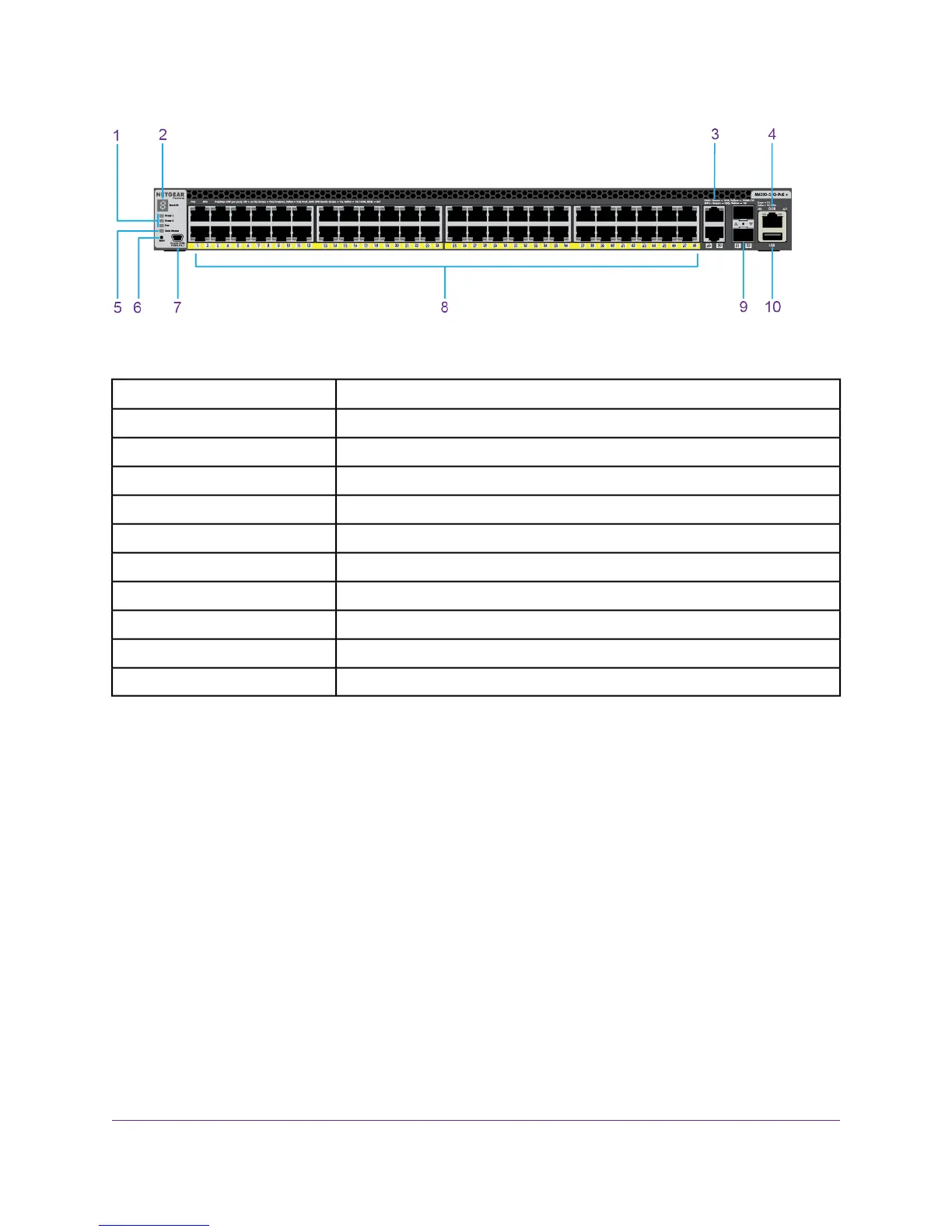
Figure 10. Front panel model M4300-52G-POE+
DescriptionNumber
Power 1, Power 2, and Fan LEDs1
Stack ID LED2
10GBASE-T ports3
OOB port4
Stack Master LED5
Reset button6
Mini USB console port7
1000BASE-T PoE+ ports8
10GBASE-X SFP+ ports9
USB port10
From left to right, the front panel of the full 1G models with 10G uplinks provides the following components:
• Stack ID, Power 1, Power 2, Fan, Stack Master, and system LEDs (see LEDs, M4300 Series 1G Models
With 10G Uplinks on page 22).
• Recessed Reset button
• One mini USB console port
• Depending on the model, twenty-four or forty-eight 10/100/1000 Mbps autosensing 1000BASE-T RJ-45
ports, each with a left LED and a right LED (see LEDs, M4300 Series 1G Models With 10G Uplinks on
page 22).
• The LED functionality depends on the model:
- Non-PoE models. On model M4300-28G and model M4300-52G, the left LED indicates the speed
and the right LED indicates the activity.
- PoE models. On model M4300-28G-POE+ and model M4300-52G-POE+, the left LED indicates
the PoE status and the right LED functions as the combined speed/activity LED
• Two dedicated 10GBASE-T autosensing ports, each with a combined speed/activity LED (see LEDs,
M4300 Series 1G Models With 10G Uplinks on page 22):
Hardware Overview
20
Managed Stackable Switch Series M4300
 Loading...