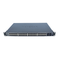
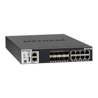
Figure 6. Back panel model M4300-24X24F
DescriptionNumber
PSU1 with AC connector1
Bay for PSU22
From left to right, the back panel of model M4300-24X24Fprovides the following components:
• Fixed fans for front-to-back air flow
• Modular bay in which an APS250W power supply unit (PSU) is installed
• Second modular bay for an optional second PSU
LEDs, M4300 Series Full 10G Models
The following table describes the LEDs on the front panel of the full 10G models.
Table 1. LEDs full 10G models
DesignationLED
Solid green.The power module is present, is supplying power to the switch, and is
functioning normally
Solid yellow. The switch is booting.
Blinking yellow. The system boot-up failed or another failure occurred
Off . Power is not supplied to the switch.
Because model M4300-24X24F can support two PSUs, the front
panel provides both a Power 1 LED and Power 2 LED.
Note
Power
• Solid green.The fans are functioning normally.
• Blinking yellow. One or more fans failed.
• Off. Power is not supplied to the switch. The fans are off.
Fan
Hardware Overview
15
Managed Stackable Switch Series M4300
 Loading...