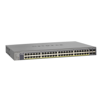
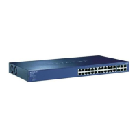
Table 2. LEDs 1G models with 10G uplinks (Continued)
DescriptionLED
Non-PoE models:
• Left side speed LED:
- Solid green. A valid 1000 Mbps link is established on the port.
- Solid yellow. A valid 10/100 Mbps link is established on the port.
- Off. No link is established on the port
• Right side activity/link LED
- Solid green. A valid link is established on the port.
- Blinking green.The port is transmitting or receiving packets
- Off. No link is established on the port.
1000BASE-T RJ-45 ports
(two LEDs per ports)
PoE models
Left side PoE status LED:
- Solid green. A PoE-powered device (PD) is connected and the port is
supplying power successfully
- Solid yellow. Indicates one of the following failures, which prevents the port
from supplying power:
* A short circuit occurred on the PoE power circuit.
* The PoE power demand exceeds the available power.
* The PoE current exceeds the PD’s classification.
* An out-of-proper voltage band condition occurred.1
- Off. A PoE-powered device (PD) is not connected to the port.
Right side speed/activity/link LED:
- Solid green. A valid 1000 Mbps link is established on the port.
- Blinking green.The port is transmitting or receiving packets at 1000 Mbps.
- Solid yellow. A valid 10/100 Mbps link is established on the port.
- Blinking yellow.The port is transmitting or receiving packets at 10/100 Mbps.
- Off. No link is established on the port.
• Off. No link is established on the copper port
• Solid green .The copper port established a valid 10 Gbps link
• Blinking green .The copper port is transmitting or receiving packets at 10
Gbps
• Solid yellow.The copper port established a valid 1 Gbps or 100 Mbps link.
• Blinking yellow.The copper port is transmitting or receiving packets at 1
Gbps or 100 Mbps.
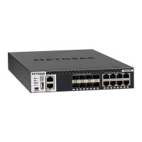
10GBASE-T RJ-45 port
(one LED per port)
Hardware Overview
24
Managed Stackable Switch Series M4300
 Loading...
