Doc# E107706 5 - 6
5: Communication Wiring
Electro Industries/GaugeTech
The Leader In Power Monitoring and Smart Grid Solutions
Electro Industries/GaugeTech
The Leader In Power Monitoring and Smart Grid Solutions
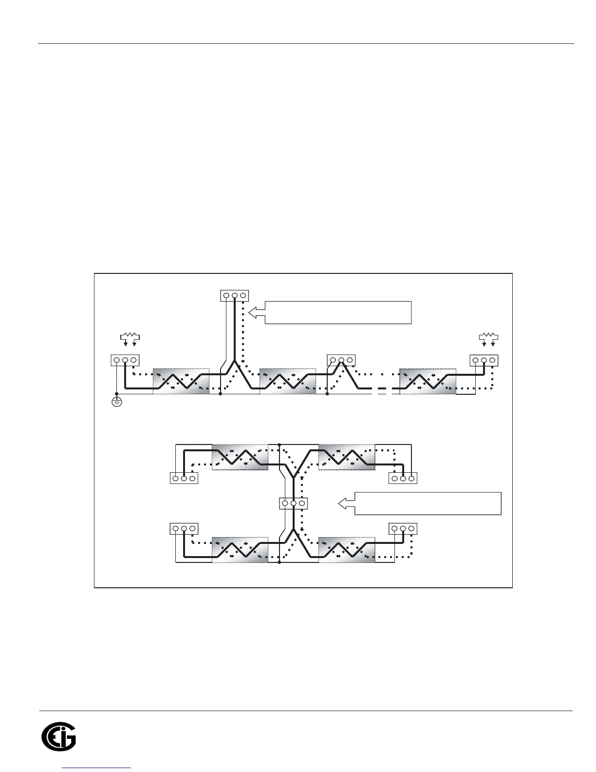
• Avoid both “star” and “tee” connections (see Figure 5.6). No more than two cables
should be connected at any one point on an RS485 network, whether the connec-
tions are for devices, converters or terminal strips.
• Include all segments when calculating the total cable length of a network. If you are
not using an RS485 repeater, the maximum length for cable connecting all devices
is 4000 feet (1219 meters).
• RT EXPLANATION: Termination Resistors are generally used on both ends of longer
length transmission lines. The value of the Termination Resistors is determined by
the electrical parameters of the cable. Use RTs only on Master and Last Slave when
connecting multiple meters in a Daisy Chain.
Figure 5.6: Incorrect “T” and “Star” Topologies
Twisted pair, shielded (SH) cable
+ - SH
+ - SH
+ - SH
Slave device 1
Slave device 2
Last Slave device N Master device
Earth Connection, preferably at
sin
le location
Twisted pair, shielded (SH) cable Twisted pair, shielded (SH) cable
Twisted pair, shielded (SH) cable
+ -SH
Twisted pair, shielded (SH) cable
Twisted pair, shielded (SH) cable Twisted pair, shielded (SH) cable
+ - SH
+- SH
+ - SH + -SH
Master device
Slave device 1 Slave device 2
Slave device 3 Slave device 4
R
R
+ - SH
Long stub results “T” connection that can cause
interference
roblem!
“STAR” connection can cause interference
roblem!